Adjustable positioning clamping mechanical hand

A technology of positioning clamping and manipulators, applied in the direction of manipulators, chucks, manufacturing tools, etc., can solve the problems of small clamping force, unsuitable for grasping test equipment, complex structure of clamping manipulators, etc., and achieve large clamping force , the effect of streamlining the structure

Pending Publication Date: 2018-08-31
昆山宇辰光通自动化科技有限公司
View PDF1 Cites 2 Cited by
  • Summary
  • Abstract
  • Description
  • Claims
  • Application Information

AI Technical Summary

Problems solved by technology

[0004] The gripping force of the gripping manipulator in the prior art is small, and the front end is generally set in the shape of pincers, which are only clamped by the friction force between the pincers and the object to be gripped, and are not suitable for gripping heavy objects. (such as 100k

Method used


Image

  • Adjustable positioning clamping mechanical hand
  • Adjustable positioning clamping mechanical hand
  • Adjustable positioning clamping mechanical hand

Examples


Embodiment

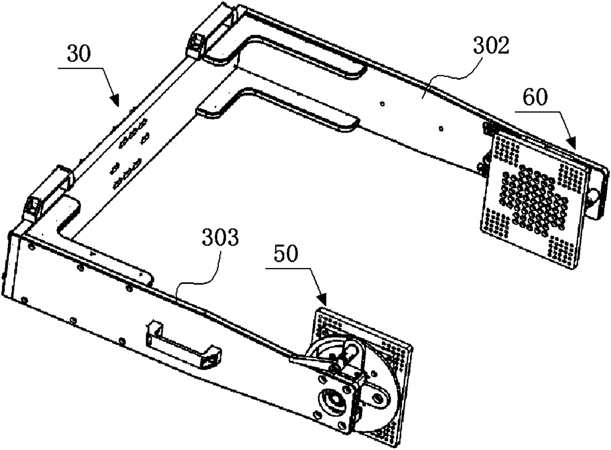
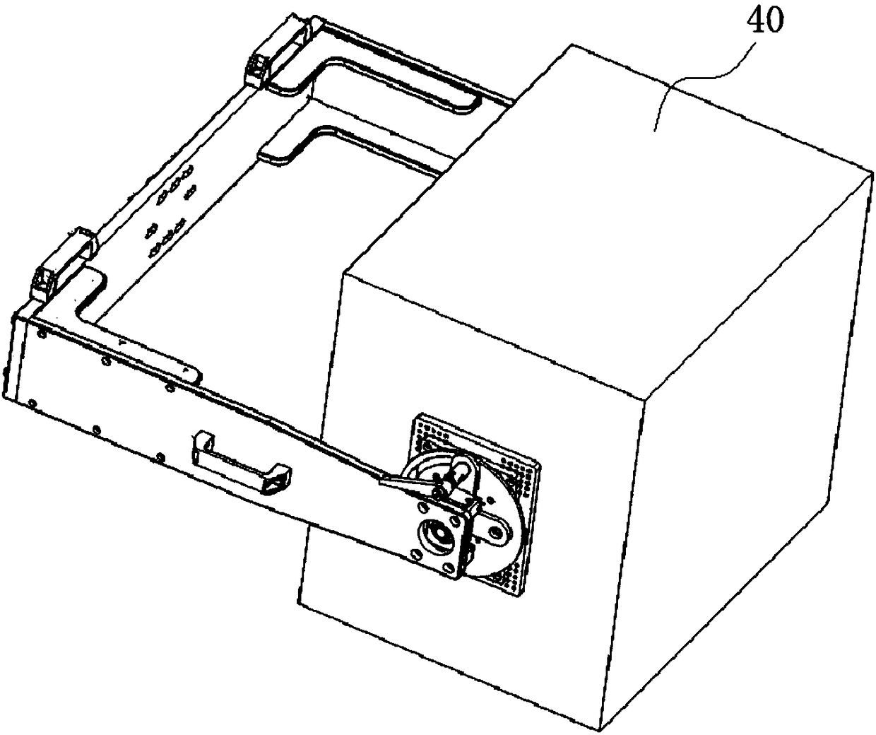
[0039] Example: An adjustable positioning and clamping manipulator, such as Figure 1 to Figure 9 As shown, a clamping arm 30 is included. The arms of the clamping arm include a left arm 302 and a right arm 303 that can clamp the device 40 to be clamped. The left arm and the right arm are parallel to each other, defining all The opening of the clamping arm is the front, and the side close to the device is the inside. One of the front end of the left arm and the front end of the right arm is provided with a first clamping mechanism 50, and the other has The second clamping mechanism 60 can fix the device to be clamped through the first clamping mechanism and the second clamping mechanism;

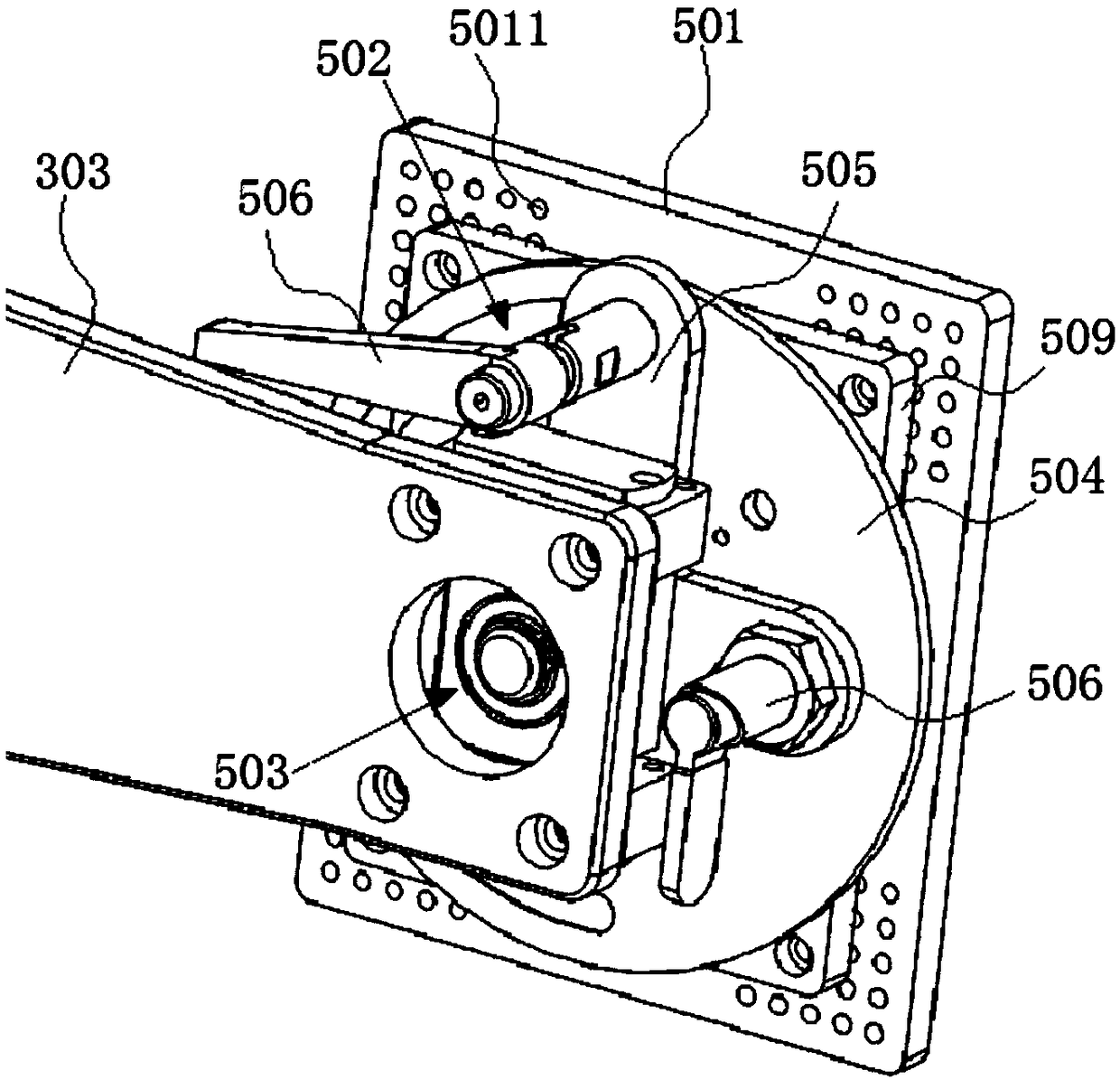
[0040] Such as image 3 As shown, the first clamping mechanism includes a first mounting plate 501, a rotating structure 502 capable of driving the first mounting plate to rotate in a vertical plane, and a rotating structure 502 capable of driving the first mounting plate to swing in a vertical...


PUM


Abstract

The invention discloses an adjustable positioning clamping mechanical hand. The adjustable positioning clamping mechanical hand comprises a clamping arm, wherein an arm of the clamping arm comprises aleft arm and a right arm; the front end of one of the left arm and the right arm is equipped with a first clamping mechanism, and the other one is provided with a second clamping mechanism, so that to-be-clamped equipment is fixed through the first clamping mechanism and the second clamping mechanism; the first clamping mechanism comprises a first mounting plate, a rotary structure capable of driving the first mounting plate to rotate in the vertical plane and a first swing structure capable of driving the first mounting plate to swing in the vertical plane; and the second clamping mechanismcomprises a second mounting plate, a buffer part, a second swing structure capable of driving the second mounting plate to swing in the vertical plane and a slide structure capable of driving the second mounting plate to horizontally move in the front-rear direction. The adjustable positioning clamping mechanical hand is simple in structure; the first clamping mechanism is matched with the secondclamping mechanism to carry out clamping, so that clamping force is great, and 100-200kg test equipment can be clamped and fixed, and proper adjustment can be performed according to a to-be-put angleof the test equipment.

Description

Technical field [0001] The invention belongs to the technical field of manipulator equipment, and particularly relates to a clamping manipulator capable of positioning. Background technique [0002] The manipulator is an automatic operating device that can imitate certain motion functions of human hands and arms to grasp, transport objects or operate tools according to a fixed program. The feature is that it can be programmed to complete various expected tasks, and its structure and performance have the advantages of both human and mechanical handpieces. [0003] Manipulators are the earliest industrial robots and the earliest modern robots. They can replace human labor to achieve mechanization and automation of production, and can operate in harmful environments to protect personal safety. Therefore, they are widely used in machinery manufacturing, metallurgy, Departments of electronics, light industry and atomic energy. [0004] The clamping force of the clamping manipulator in t...

Claims


Application Information

Patent Timeline
IPC IPC(8): B25J15/08
CPCB25J15/0028B25J15/08
Inventor 张英乾张博谭小龙
Owner 昆山宇辰光通自动化科技有限公司
Why Eureka
Try Eureka