
Mounting structure for wall-to-wall connection and its assembly and disassembly methods

An installation structure and hinged technology, which is applied in the direction of walls, building components, building structures, etc., can solve the problems of large number of vertical connection surfaces, long construction period, and large engineering volume, so as to improve installation efficiency, improve connection strength, The effect of improving stability

Active Publication Date: 2019-05-17
CHONGQING UNIV
View PDF9 Cites 0 Cited by
  • Summary
  • Abstract
  • Description
  • Claims
  • Application Information

AI Technical Summary

Problems solved by technology

[0002] In prefabricated buildings, the walls other than the load-bearing walls are generally prefabricated walls. For the connection between prefabricated walls, the method of grouting is generally used to make the vertical connection between the walls. A prefabricated wall is due to the transportation and hoisting conditions. Restrictions, need to be decomposed into several transport units, resulting in a large number of vertical connection surfaces that need to be grouted and spliced ​​on site. If wet work (grouting) is still used to connect, the project volume will be large and the construction period will be long

Method used


Image

  • Mounting structure for wall-to-wall connection and its assembly and disassembly methods
  • Mounting structure for wall-to-wall connection and its assembly and disassembly methods
  • Mounting structure for wall-to-wall connection and its assembly and disassembly methods

Examples


Embodiment Construction

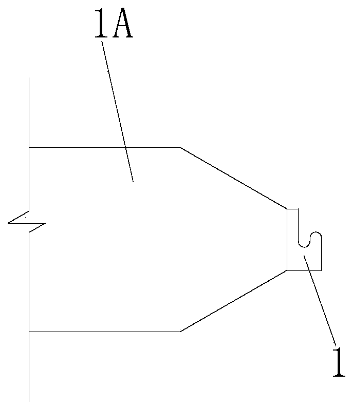
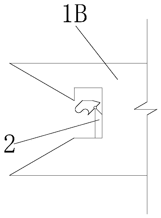
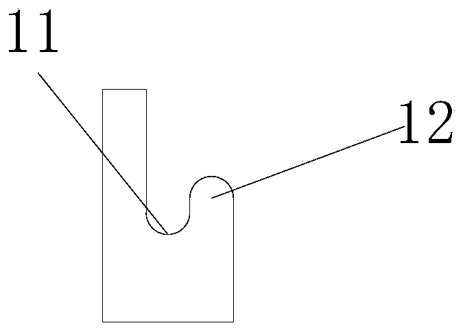
[0041] Such as figure 1 and figure 2 As shown, an installation structure for wall-to-wall connection includes a concave wall with a tenon on one side and a convex wall with a tenon that can be engaged with the tenon on one side; the tenon and tenon They are all vertically arranged; on the side of the tenon relative to the tenon groove, there are several fixed clips with slots at intervals along the vertical direction; corresponding movable clips are provided in the mortise corresponding to each fixed clip ;Such as Figure 4As shown, the movable clamping piece includes a movable clamping block and a support fixed in the mortise. The movable clamping block is hinged on the support and can rotate horizontally around the hinge point. One end of the movable clamping block is provided with a The clip in the draw-in slot of the fixed clip; also includes the clip that can keep the clip of the movable clip facing the draw-in slot of the fixed clip and makes the hinged side of the mo...


PUM


Abstract

The invention discloses a mounting structure used for the connection between walls. The structure comprises a concave wall provided with a tenon groove and a convex wall provided with a convex tenon;the convex tenon is provided with a plurality of fixing clamping parts provided with champing grooves along a vertical direction at intervals; the tenon groove is internally provided with corresponding movable clamping parts corresponding to the fixing clamping parts; each movable clamping part comprises a movable clamping block and a supporting seat fixed in the tenon groove, each movable clamping block is hinged on the supporting seat and can horizontally rotate around a hinge joint , and one end of each movable clamping block is provided with a clamping head capable of being clamped in a clamping groove of the corresponding fixing clamping part; each movable clamping part further comprises a clamping groove and a resetting mechanism, wherein the clamping grooves can keep the clamping heads of the movable clamping blocks facing the fixing clamping parts when the movable clamping blocks are in an original state, and the resetting mechanism can make a hinged side of the movable clamping block opened relative to the supporting seat. The invention further provides an assembly method and detachment method, when the structure is assembled, it is only needed to push the clamping tenon of the convex wall into the tenon groove of the concave wall; when the structure is detached, it is only needed to pull the clamping tenon of the convex wall out of the tenon groove of the concave wall. The mounting structure used for the connection between walls and the assembly and detachment methods thereof have the advantages that non-wetness operation is achieved, the detachable connection between the walls is achieved, and the lossless detachment is achieved.

Description

technical field [0001] The invention relates to the technical field of prefabricated buildings, in particular to a pre-embedded assembly for connecting beams and walls used in prefabricated buildings. Background technique [0002] In prefabricated buildings, the walls other than the load-bearing walls are generally prefabricated walls. For the connection between prefabricated walls, the method of grouting is generally used to make the vertical connection between the walls. A prefabricated wall is due to the transportation and hoisting conditions. Restrictions, it needs to be broken down into several transport units, resulting in a large number of vertical connection surfaces that need to be grouted and spliced ​​on site. If wet work (grouting) is still used to connect, the project volume will be large and the construction period will be long. Contents of the invention [0003] Aiming at the deficiencies in the prior art above, the present invention provides an installation...

Claims


Application Information

Patent Timeline
Patent Type & Authority Patents(China)
IPC IPC(8): E04B2/00
CPCE04B2/00
Inventor 谭俨珂唐诗怡杨雅婷曹永红李国荣
Owner CHONGQING UNIV
Learn More