Check patentability & draft patents in minutes with Patsnap Eureka AI!

Hydraulic retarder transmission control mechanism

A technology of hydraulic retarder and transmission control, which is applied to transmission parts, brake discs, mechanical equipment, etc., can solve problems affecting vehicle power and economy, and achieve novel structure, reasonable design, and outstanding substance Effect

Active Publication Date: 2018-08-31
HEFEI UNIV OF TECH +1
View PDF4 Cites 4 Cited by
  • Summary
  • Abstract
  • Description
  • Claims
  • Application Information

AI Technical Summary

Problems solved by technology

[0005] The invention provides a hydraulic retarder transmission control mechanism, the purpose of which is to solve the problem that the transmission connection mode of the existing retarder affects the power and economy of the vehicle, and on the premise of ensuring the transmission and reliable operation of the hydraulic retarder , so that its impact on vehicle dynamics and economy in non-working conditions is improved

Method used


Image

  • Hydraulic retarder transmission control mechanism
  • Hydraulic retarder transmission control mechanism
  • Hydraulic retarder transmission control mechanism

Examples


Embodiment

[0020] Embodiment: A hydraulic retarder transmission control mechanism

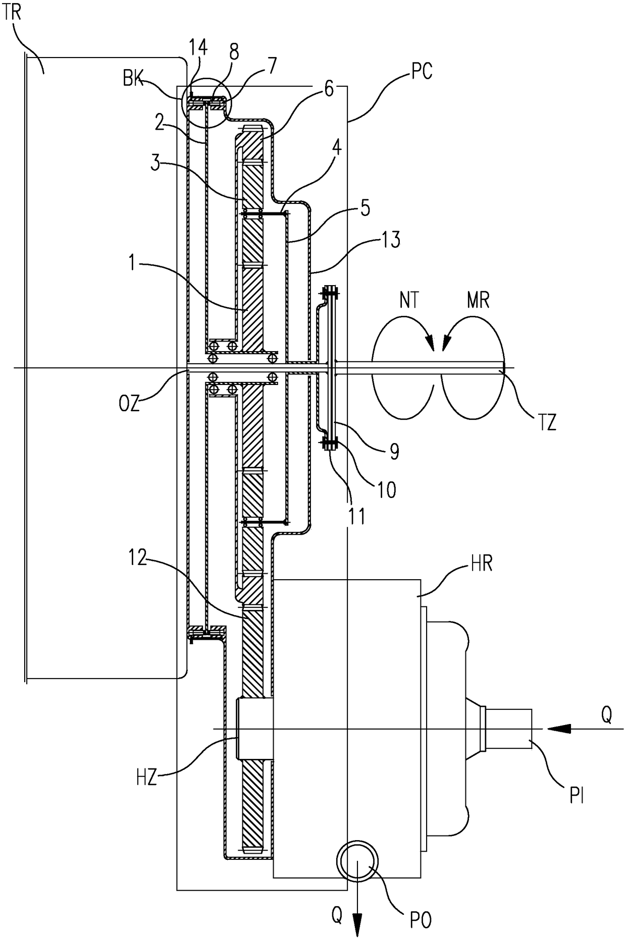
[0021] The transmission control mechanism of the hydraulic retarder combines or interrupts the power transmission of the transmission shaft to the hydraulic retarder by controlling the brake piston to brake or release the brake on the brake disc. The structure and working principle of the transmission control mechanism of the hydraulic retarder will be described in detail below in conjunction with the accompanying drawings.

[0022] Such as figure 1 , figure 2 , image 3 As shown, the hydraulic retarder transmission control mechanism PC is composed of an NGW planetary gear mechanism, a brake BK, a retarder input gear 12 and a transmission control mechanism housing 13, which are described as follows:

[0023] 1. NGW planetary gear mechanism

[0024] Such as figure 1 As shown, in this embodiment, the NGW planetary gear mechanism is composed of a sun gear 1 , a planetary carrier, more than two planetar...


PUM


Abstract

The invention discloses a hydraulic retarder transmission control mechanism. The mechanism is characterized by comprising a planet gear mechanism, a brake and a transmission control mechanism shell; the planet gear mechanism is composed of a sun gear, a planet carrier, a disc-shaped gear ring and two or more than two planet gears; the brake comprises a brake disc and a brake part; and the sun gearserving as a retardance fixing end of the planet gear mechanism is fixedly connected with the brake disc, the disc-shaped gear ring serving as the retardance output end of the planet gear mechanism is in transmission connection with a retarder shaft, and the planet carrier serving as the retardance input end of the planet gear mechanism is in transmission connection with a transmission shaft of avehicle or / and a transmission output shaft. According to the mechanism, the problem that a transmission connection mode of an existing retarder affects vehicle power and economy is solved, and on thepremise that the transmission and the reliable work of the hydraulic retarder are guaranteed, the influence of the hydraulic retarder in the non-working state on the power performance and the economical efficiency of the vehicle is improved.

Description

technical field [0001] The invention belongs to a retarding braking system of a vehicle, in particular to a control mechanism for controlling the retarding braking force transmission of a hydraulic retarder. Background technique [0002] The driving vehicle uses the service brake to decelerate or stop, especially for road passenger and cargo transport vehicles with a large passenger capacity and a large cargo capacity, when encountering a long-distance downhill, the vehicle speed must be controlled by braking to ensure Driving safety. At present, mechanical friction brakes of various structures are mainly used on vehicles. Under long-term braking conditions, this type of brake will cause the temperature of the friction brake pair to rise due to friction, performance attenuation, and braking performance. Therefore, the auxiliary braking system and the mechanical braking system on the vehicle can effectively improve the braking effect, reduce or avoid the failure of the mecha...

Claims


Application Information

Patent Timeline
IPC IPC(8): F16D65/12F16H57/08
CPCF16D65/12F16H57/08
Inventor 汪韶杰杨瑞恒曹文达陈杰峰侯郭顺施益平孙保群盛楠夏光郑友闫瑞琦滑杨莹郭冬云
Owner HEFEI UNIV OF TECH
Features
  • R&D
  • Intellectual Property
  • Life Sciences
  • Materials
  • Tech Scout
  • Unparalleled Data Quality
  • Higher Quality Content
  • 60% Fewer Hallucinations
Learn More