A turning guide device for construction engineering cable erection

A technology of construction engineering and guiding devices, applied in the direction of cable laying equipment, etc., can solve problems such as low efficiency, chaotic cable arrangement, difficult to bend cables, etc., and achieve the effect of fast completion, simple operation, and easy disassembly

Active Publication Date: 2020-06-16
深圳市松立建设集团有限公司
View PDF7 Cites 0 Cited by
  • Summary
  • Abstract
  • Description
  • Claims
  • Application Information

AI Technical Summary

Problems solved by technology

[0002] In the building installation project, the cable erection project, which is the main sub-item of the electrical installation part, is generally affected by conditions such as erection conditions, applicability of tools and equipment, and level of mechanized equipment, and there are generally problems of low efficiency and low project quality. Damage, twisting and confusion of cables due to unrelieved stress during erection are more common
At present, for the cable erection work on the cable bridge, many construction units are at the 90° turn of the cable bridge during construction, and the cables are not easy to turn in the bridge.

Method used


Image

  • A turning guide device for construction engineering cable erection
  • A turning guide device for construction engineering cable erection
  • A turning guide device for construction engineering cable erection

Examples


Embodiment Construction

[0021] The following will clearly and completely describe the technical solutions in the embodiments of the present invention with reference to the accompanying drawings in the embodiments of the present invention. Obviously, the described embodiments are only some, not all, embodiments of the present invention.

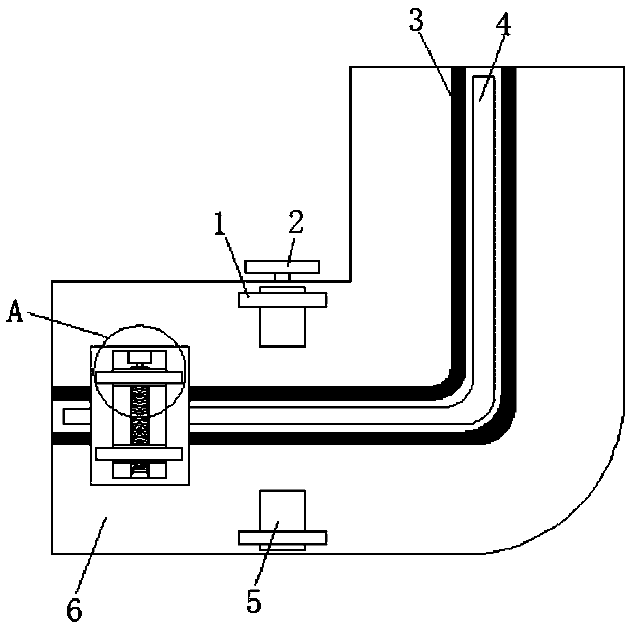
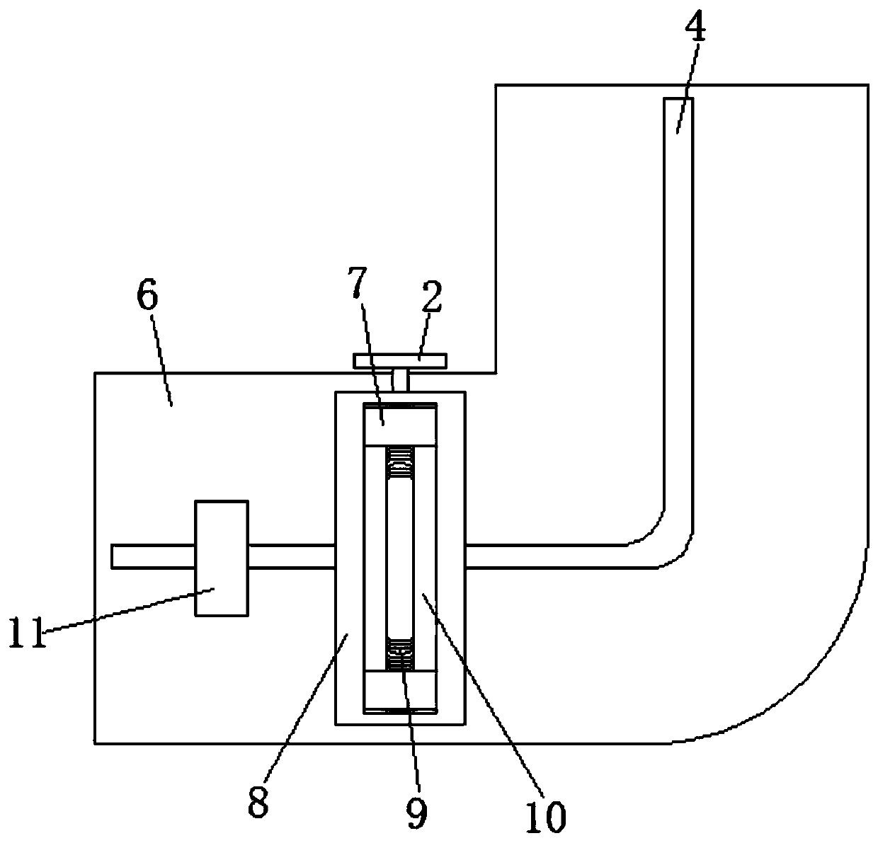
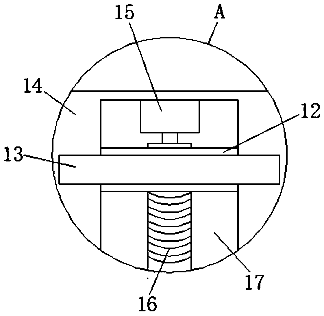
[0022] refer to Figure 1-4 , a construction engineering cable erection turning guide device, comprising an L-shaped device plate 6, the back of the L-shaped device plate 6 is fixedly connected with a U-shaped slide rail 3, the U-shaped slide rail 3 is L-shaped, and the side of the U-shaped slide rail 3 The wall is slidingly connected with a slide plate 14, the side wall of the slide plate 14 is provided with a device groove 17, the inner wall of the device groove 17 is fixedly connected with a drive motor 15, and the end of the output shaft of the drive motor 15 is fixedly connected with a first double-ended threaded rod 16, the first The other end of the double-end...


PUM


Abstract

The invention discloses a turning and guiding device for cable erection in architectural engineering. The device comprises an L-shaped device plate, wherein a U-type sliding rail is fixedly connectedto the back of the L-shaped device plate and is L-shaped, a sliding plate is glidingly connected to the side wall of the U-type sliding rail, a device groove is formed in the side wall of the slidingplate, a driving motor is fixedly connected with the inner wall of the device groove, the tail end of an output shaft of the driving motor is fixedly connected with a first double threaded rod, the other end of the first double threaded rod is rotationally connected with the inner wall of the device groove, upper and lower ends of the first double threaded rod are in threaded connection with two connecting rods, one end of each of the two connecting rods is glidingly connected with the inner wall of the device groove, the side walls of the other ends of the two connecting rods are fixedly connected with clamp plates, and an L-shaped hole is formed in the inner wall of the U-type sliding rail. The device is reasonable in structure and simple to operate and can rapidly realize 90-degree turning of a cable in a cable tray.

Description

technical field [0001] The invention relates to the technical field of cable erection, in particular to a turning guide device for cable erection in construction engineering. Background technique [0002] In the building installation project, the cable erection project, which is the main sub-item of the electrical installation part, is generally affected by conditions such as erection conditions, applicability of tools and equipment, and level of mechanized equipment, and there are generally problems of low efficiency and low project quality. In the erection process, damage, twisting and disorder of cable arrangement due to unrelieved stress are more common. At present, many construction units are in the 90° turn of the cable bridge during construction for the cable erection work on the cable bridge, and the cables are not easy to turn in the bridge. Contents of the invention [0003] The purpose of the present invention is to solve the shortcomings in the prior art, and ...

Claims


Application Information

Patent Timeline
Patent Type & Authority Patents(China)
IPC IPC(8): H02G1/06
CPCH02G1/06
Inventor 黎允仪
Owner 深圳市松立建设集团有限公司
Why Eureka
Try Eureka