Motor with convenient-to-detach cooling device

A technology for convenient disassembly and cooling devices, which is applied in the direction of cooling/ventilation devices, electromechanical devices, electrical components, etc., which can solve the problems of inconvenient disassembly of cooling devices, failure to meet the heat dissipation requirements of motors, and reduce the temperature, so as to reduce temperature and reduce water resources Waste, the effect of increasing the contact area

Active Publication Date: 2018-08-31
JIAMUSI ELECTRIC MACHINE
View PDF6 Cites 1 Cited by
  • Summary
  • Abstract
  • Description
  • Claims
  • Application Information

AI Technical Summary

Problems solved by technology

[0003] The object of the present invention is: in order to solve the problem that the cooling device of the existing motor is inconvenient to disassemble, and the built-in heat dissipation device of the motor cannot meet the heat dissipation requirements of the motor in a high temperature environment, the present invention provides a motor with a cooling device that can be easily disassembled. Its purpose is to increase the heat dissipation efficiency of the motor by adding a cooling device in a high-temperature environment, so as to avoid the continuous rise of the temperature of the motor, burn out the winding group, and reduce the service life of the motor

Method used


Image

  • Motor with convenient-to-detach cooling device
  • Motor with convenient-to-detach cooling device
  • Motor with convenient-to-detach cooling device

Examples


Embodiment Construction

[0034] In order for those skilled in the art to better understand the present invention, the present invention will be further described in detail below with reference to the accompanying drawings and the following embodiments.

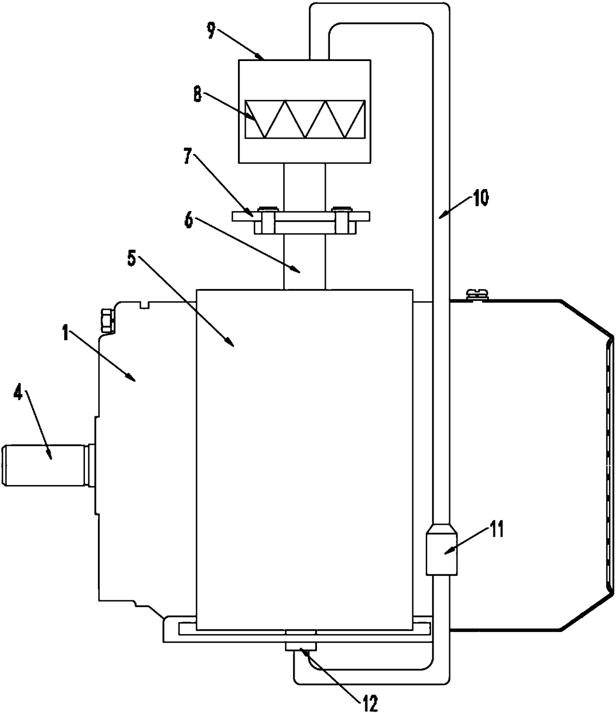
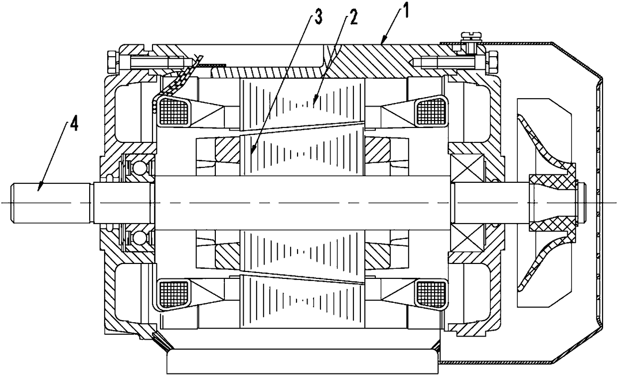
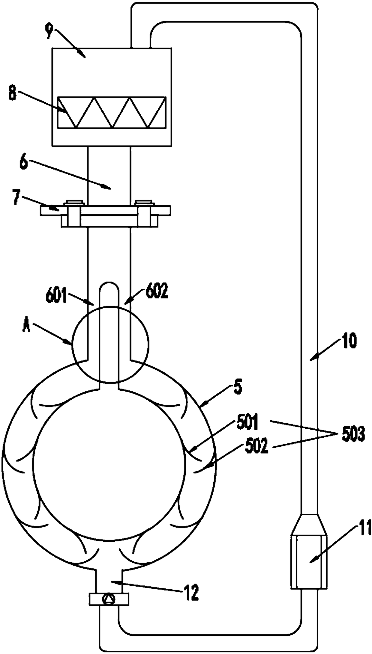
[0035] The convenient disassembly motor of the cooling device of the present invention includes a housing 1 in which a rotating shaft 4 is arranged, the rotating shaft 4 is sheathed with a conical rotor 3, and the inner wall of the housing 1 is provided with a conical rotor 3 The stator 2 matched with each other, the outer shell 1 is sleeved with an annular water-cooling layer 5, the upper end of the water-cooling layer 5 is provided with a water inlet pipe 6, and the lower end of the water-cooling layer 5 is provided with a water outlet 12, the The lower end of the water inlet pipe 6 is separated to form a first water inlet pipe 601 and a second water inlet pipe 602 that are independent of each other. The inner wall of the water-cooling layer 5 is provid...


PUM


Abstract

The invention discloses a motor with a convenient-to-detach cooling device, and belongs to the technical field of motor devices. The motor is used for solving the problems that a cooling device of anexisting motor is not convenient to detach and the built-in cooling device of the motor under the high temperature environment cannot meet the cooling requirements of the motor. The motor comprises ashell. A rotating shaft is arranged in the shell and sleeved with a conical rotor. A stator matched with the conical rotor is arranged on the inner wall of the shell. The motor is characterized in that the outer side of the shell is sleeved with an annular water-cooling layer, a water inlet pipe is arranged at the upper end of the water-cooling layer, a water outlet is formed in the lower end of the water-cooling layer, the lower end of the water inlet pipe is divided into a first water inlet pipe and a second water inlet pipe which are independent of each other, and a plurality of flow guidepieces are arranged on the inner wall of the water-cooling layer and are inclined in the water flow direction to form an arc-shaped pit.

Description

Technical field [0001] The invention relates to the technical field of motor devices, and more specifically to a motor with a cooling device that is convenient to disassemble. Background technique [0002] Motor refers to an electromagnetic device that realizes the conversion or transmission of electric energy according to the law of electromagnetic induction. Its main function is to generate driving torque. As the power source of electrical appliances or various machinery, the use of motors has been integrated into all aspects of life. The heat dissipation device of the motor is usually equipped with one or more cooling fans inside the motor. The heat generated during the working process of the motor is transferred to the shell through the cooling fan and then transferred to the outside of the motor, so as to prevent the motor temperature from being too high and causing the insulation layer It is easy to age, easy to burn the coil, and reduce the service life of the motor. At pr...

Claims


Application Information

Patent Timeline
Patent Type & Authority Applications(China)
IPC IPC(8): H02K5/20H02K9/19
CPCH02K5/20H02K9/19Y02T10/64
Inventor 杨志伟
Owner JIAMUSI ELECTRIC MACHINE
Why Eureka
Try Eureka