
Supply of electric energy to a electrically driven vessel

A ship and electric energy technology, applied in battery/battery traction, engine-driven traction, electric vehicles, etc., can solve the problems of complicated and time-consuming cable control

Active Publication Date: 2018-08-31
ABB (SCHWEIZ) AG
View PDF9 Cites 6 Cited by
  • Summary
  • Abstract
  • Description
  • Claims
  • Application Information

AI Technical Summary

Problems solved by technology

Also, cable handling is complicated and time consuming due to weight and cable size

Method used


Image

  • Supply of electric energy to a electrically driven vessel
  • Supply of electric energy to a electrically driven vessel
  • Supply of electric energy to a electrically driven vessel

Examples


Embodiment Construction

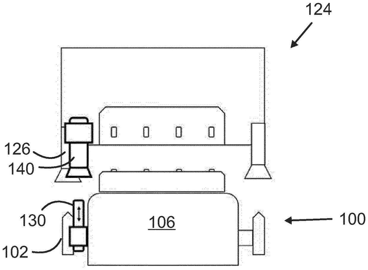
[0016] Embodiments relate to ships. The embodiments emphasize the invention with reference to road commuter ferries, but the inventive concepts are applicable to other sea-going vessels as well. Embodiments relate to a vessel equipped with mechanical docking means for mechanical docking of the vessel to a quay. The mechanical docking members of the ship and the quay are such that they mechanically engage each other as the ship approaches the quay. In an embodiment, a horizontal or vertical protrusion in one of the vessel or dock may be provided which is received by a socket or space in the other.

[0017] In one embodiment, the mechanical docking members comprise horns, which may be rigid tube feet or cone tipped beams, which are inserted into sockets in the dock to mechanically align the vessel / ferry with the loading ramp.

[0018] In another embodiment, there may be a vertical protrusion in the dock which is to be received in a receptacle of a vessel. Other mechanical con...


PUM


Abstract

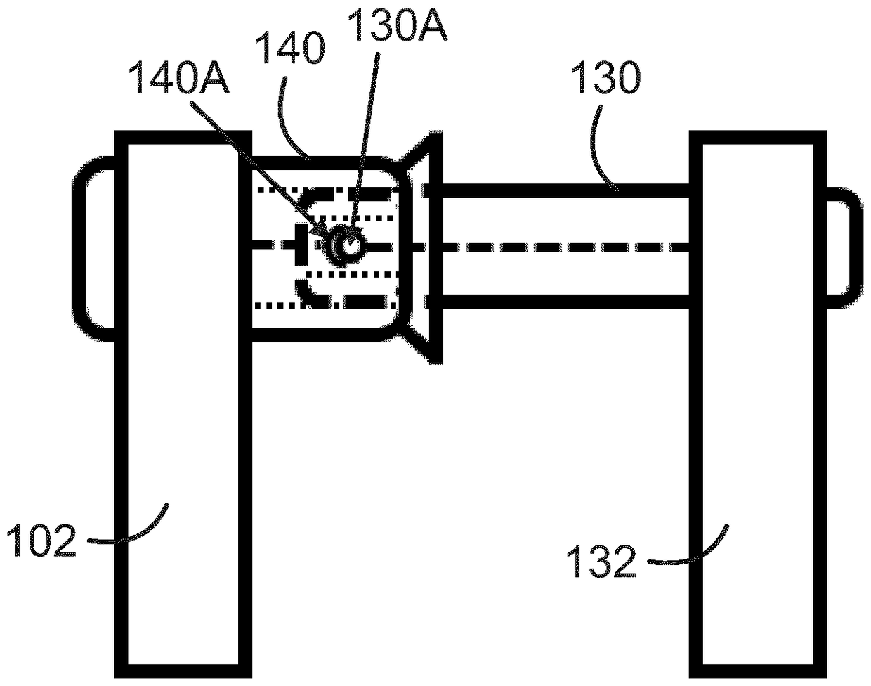
A docking arrangement for docking a vessel to a pier, comprising docking members (102, 126) for mechanical docking of the vessel to the pier (120), and electric connectors (130A, 140A) for transmission of electric energy during docking of the vessel (100) to the pier (120). The electric connectors (130A, 140A) of the vessel and the pier are positioned such that they align to each other during mechanical docking of the vessel to the pier.

Description

technical field [0001] The invention relates to the power supply of vessels such as road and commuter ferries. Background technique [0002] Interest in utilizing energy storage technologies onboard roads and commuter ferries is rapidly increasing. Viable battery solutions range from primary energy sources to peak load shedding and backup purposes. Fast charging during turnaround is an important part of battery operation, especially when used to power the main propulsion. [0003] Standardized solutions for shore connections are typically based on flexible portable cables and plugs that are manually connected to the onboard inlets on board the vessel. Since the connection procedure takes time, these are intended and better suited for longer turnaround cycles. Again, the power ratings for such solutions are rather small. [0004] Road ferries sail non-stop between shore stations at least during high traffic times. The ship is only docked during unloading and loading of c...

Claims


Application Information

Patent Timeline
Patent Type & Authority Applications(China)
IPC IPC(8): B60L11/18H02G11/00B63J99/00B60L50/15
CPCB60L2200/32B63B35/54B63J2003/043B60L53/36B60L50/61H01R13/631H01R2201/26Y02T10/62Y02T10/70Y02T10/7072Y02T90/12B63J3/04H02J5/00B63H21/17H02J7/02Y02T90/14
Inventor P.普赞海墨
Owner ABB (SCHWEIZ) AG
Learn More