

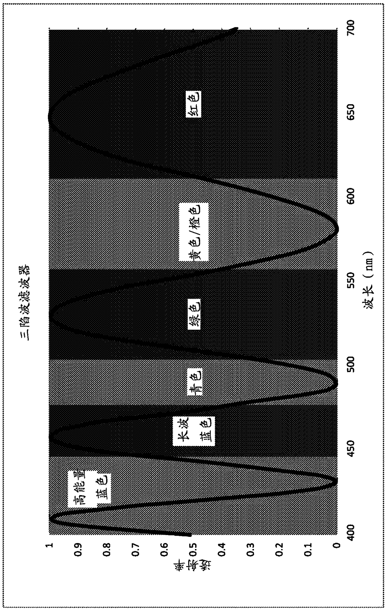
Optical filter with color enhancement
A blue and spectral technology, applied in optics, optical components, optical components, etc., can solve problems such as unrealistic glasses products
- Summary
- Abstract
- Description
- Claims
- Application Information
AI Technical Summary
Problems solved by technology
Method used
Image

Examples
example 1
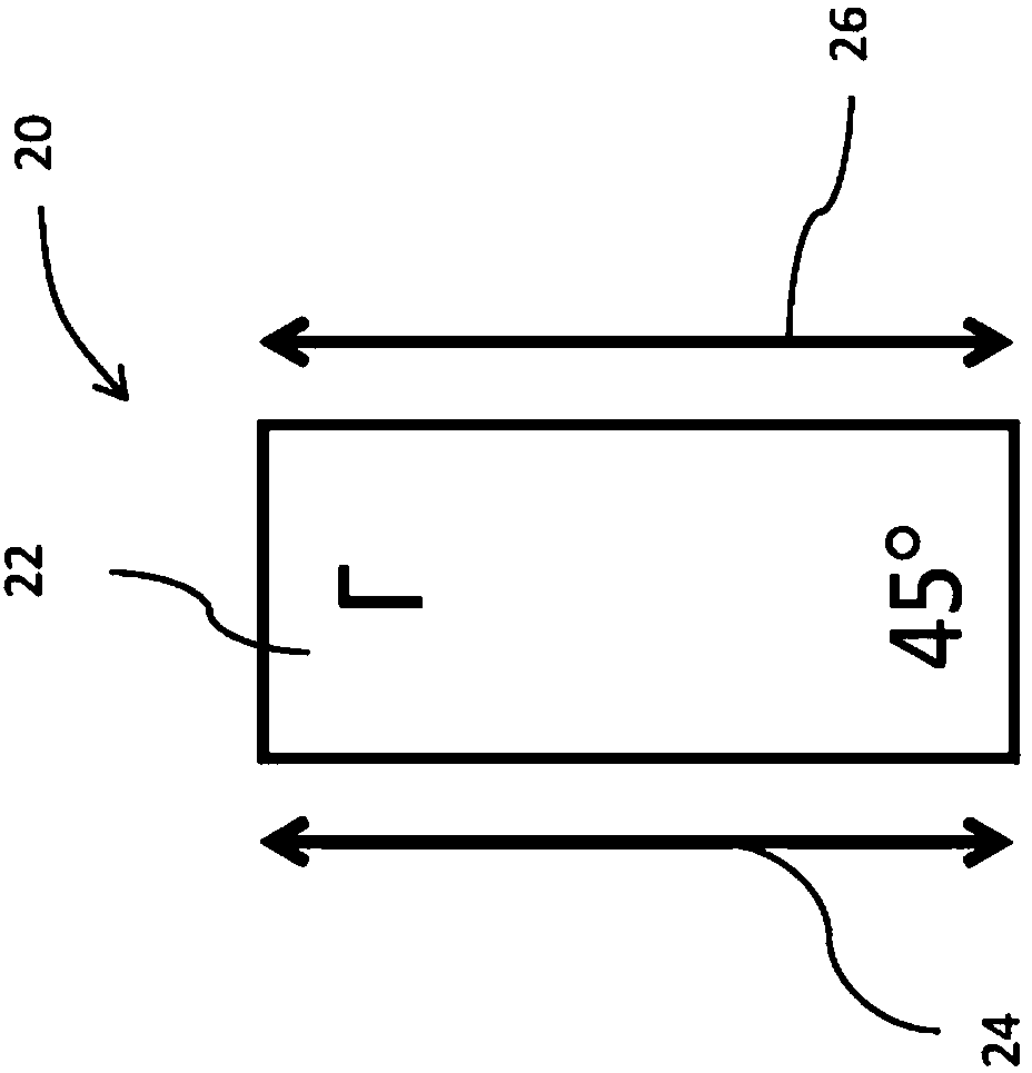
[0116] Example 1 Single-layer uniaxial PC retarder with parallel polarizers
[0117]This example is the simplest structure using a single layer of uniaxial PC film between parallel polarizers. It serves as a baseline for achievable performance without requiring additional action. Table 2 shows the output characteristics at normal incidence and at 30 degrees off azimuth for specific key azimuth angles. The L value is the effect of the filter transmission function on the luminance of the adapted light, assuming unpolarized light and a perfect unity transmission polarizer (ie only sinusoidal contribution). Because of this, L values with zero lag oscillate at 50% at low orders and converge to 25% at very high orders.
[0118] The ΔL value is the change in luminance as a percentage of the normal incidence value. The color coordinates of the white point are in xy space. The shift of the white point out of position relative to the normal incident white point coordinates is gi...
example 2
[0125] Example 2 Widefield filter using a single zero-order HW
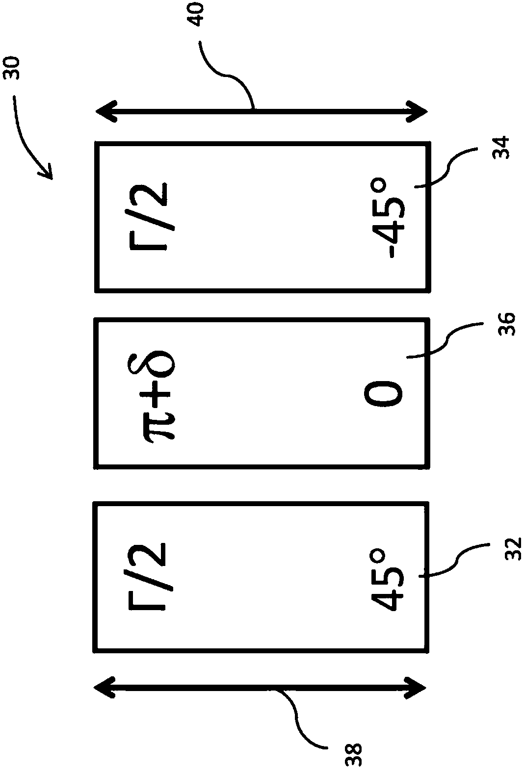
[0126] The simplest widefield form of the technique taught here is a zero-order HW retarder parallel / perpendicular to the polarizer absorption axis between beam-splitting multi-stage retarders. image 3 The configuration is shown. This example uses beam-splitting retarders, each with a retardation of 2.5 waves at 532nm. A zero-order HW retarder with a center wavelength of 535 nm was used to balance the optical density of the cyan and yellow minima at normal incidence. The polarizers are parallel.
[0127] If the HW retarder were perfectly achromatic, the normal incidence performance would closely match Table 1. The effects of HW retarder dispersion include loss of optical density at null, loss of peak transmission, and incremental spectral shift, all of which contribute to chromaticity changes. Thus, there is a required sacrifice even in normal incidence spectral performance in order to obtain uniformity wi...
example 3
[0130] Example 3 Widefield filter using a double-layer rotator
[0131] Figure 4 Another design shown uses a double-layer rotator as a means of broadening the filter 50 . The benefit of increasing the number of HW retarders is that the center polarization shift can be made less colored above visible light. In this case, as Figure 4 As shown in , two zero-order HW films 52 and 54 are arranged between beam-splitting retarders ( 56 and 58 ), which are then between polarizers 60 and 62 . The two HW retarders have the appearance of effectively rotating the polarizer 90 degrees, so peaks and minima are swapped. This inversion can be counteracted by each of the beam-splitting retarders plus / minus a quarter-wave delay (majorly shown in the figure). To the extent that the rotator is achromatic over visible light, it presents the same situation as the crossed polarizer case. However, the transformation is not fully achromatic, so the parallel polarizer case with each external e...
PUM
| Property | Measurement | Unit |
|---|---|---|
| Transmittance | aaaaa | aaaaa |
Abstract
Description
Claims
Application Information