Supercharge Your Innovation With Domain-Expert AI Agents!

Stator coil, method for manufacturing stator, and dynamo-electric machine

A stator coil and manufacturing method technology, applied in the direction of manufacturing motor generators, prefabricated windings embedded in motors, electrical components, etc., can solve the problems of difficult mechanization, difficult operation mechanization, and difficulty in preventing stator coils from being enlarged, and achieve the goal of preventing large-scale Effect

Inactive Publication Date: 2018-08-31
AISIN AW CO LTD +1
View PDF7 Cites 0 Cited by
  • Summary
  • Abstract
  • Description
  • Claims
  • Application Information

AI Technical Summary

Problems solved by technology

[0007] However, wiring (or wiring replacement) after arranging one single-layer laminated coil and the other single-layer laminated coil on the stator core needs to be done manually, and it is not easy to mechanize (automate).
In addition, for wiring (or wiring replacement), it is necessary to secure a space for arranging joint terminals and insulating members, so there is a problem that the size of the stator coil (rotating machine) is increased.
Therefore, in the stator coil having the above configuration, it is difficult to prevent the enlargement of the stator coil (rotating electric machine) and to mechanize (automate) the work of arranging the stator coil to the cog slots.

Method used


Image

  • Stator coil, method for manufacturing stator, and dynamo-electric machine
  • Stator coil, method for manufacturing stator, and dynamo-electric machine
  • Stator coil, method for manufacturing stator, and dynamo-electric machine

Examples


no. 1 approach

[0037] (Structure of rotating electrical machine)

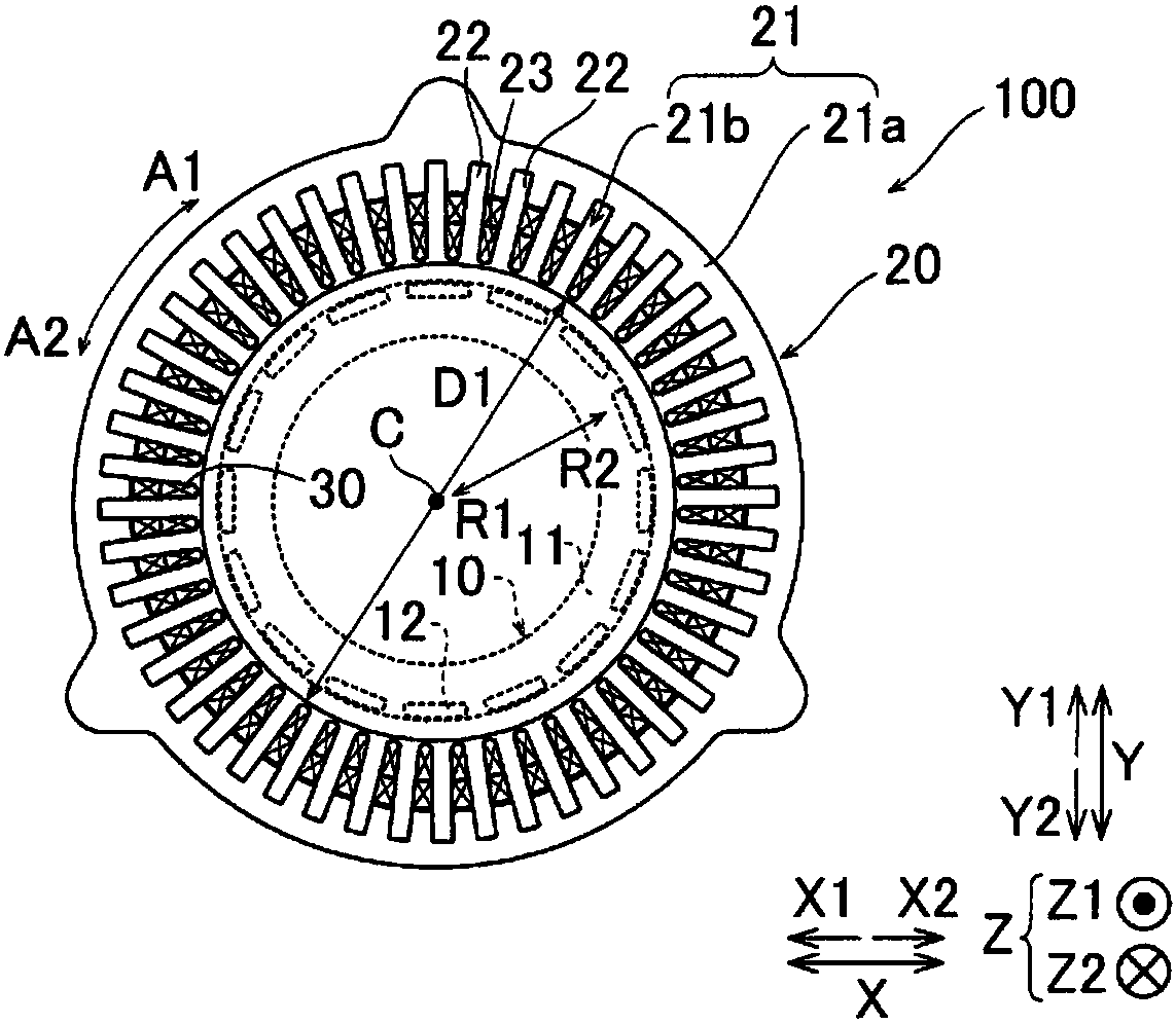
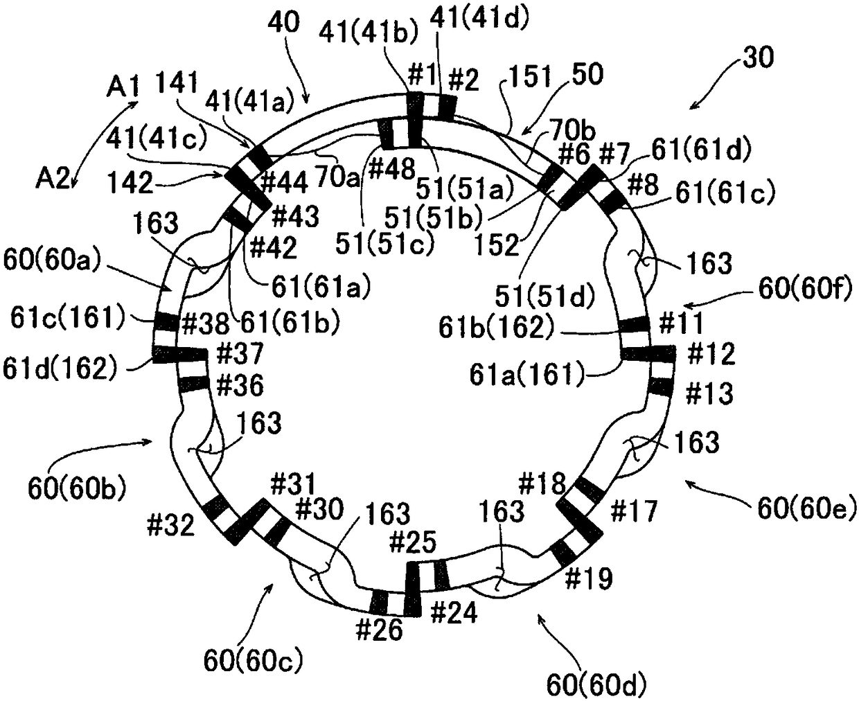
[0038] refer to Figure 1 to Figure 5 , the structure of the rotating electric machine 100 of the first embodiment will be described. figure 1 The illustrated rotating electric machine 100 is, for example, a motor (preferably a three-phase brushless motor). in addition, figure 2 One phase coil 30 of the three phase coils 30 is shown. In addition, the coil 30 is an example of the "stator coil" of a claim.

[0039] In addition, in the present specification, when only "rotation axis direction" or "axial direction" is described, it means the rotation axis direction of the rotary electric machine 100, and means the direction parallel to the Z-axis in the figure. In addition, when only "circumferential direction" is described, it means the circumferential direction of the rotating electric machine 100, and it means the arrow A1 direction or the arrow A2 direction in a figure. When only "radial direction" is described, it refe...


PUM


Abstract

This dynamo-electric machine includes a coil, and the coil includes: a first coil section composed of a single-layered lap-wound coil disposed at the outside diameter side of a slot; a second coil section composed of a single-layered lap-wound coil disposed at the inside diameter side of a slot and connected in continuous fashion to a first crossover section, which is connected in continuous fashion to the first coil section; and a third coil section group that includes a plurality of third coil sections composed of double-layered lap-wound coils.

Description

technical field [0001] The present invention relates to a stator coil, a method of manufacturing the stator, and a rotating electric machine. Background technique [0002] Conventionally, there is known a rotating electric machine including a double-layered winding coil, in which one of a pair of slot accommodations arranged in a slot in the coil is located radially outside of the slot, and one of the pair of slot accommodations is arranged outside the slot. The other one is arranged on the radial inner side of the tooth groove. Such a rotating electric machine is disclosed, for example, in JP-A-2009-195004. [0003] In the rotating electric machine described in Japanese Unexamined Patent Application Publication No. 2009-195004, among the two double-layered winding coils arranged adjacently, the cog space housing portion of one double-layer winding coil is arranged radially outside the tooth groove, and the other double-layer winding coil The slot accommodation portion of ...

Claims


Application Information

Patent Timeline
Patent Type & Authority Applications(China)
IPC IPC(8): H02K3/28H02K15/06
CPCH02K1/148H02K3/28H02K15/066H02K1/165H02K1/2753H02K3/12H02K15/024H02K15/03H02K15/0464H02K15/065H02K23/30
Inventor 畔柳彻梶田効保母贵彦
Owner AISIN AW CO LTD
Features
  • R&D
  • Intellectual Property
  • Life Sciences
  • Materials
  • Tech Scout
  • Unparalleled Data Quality
  • Higher Quality Content
  • 60% Fewer Hallucinations
Learn More