Rolling mop
A mop and roller technology, applied in the field of mops, can solve the problems of poor decontamination and cleaning effect, limited promotion and use, etc., and achieve the effects of reducing the number of rinses, good cleaning effect, and increased cleaning effect.
- Summary
- Abstract
- Description
- Claims
- Application Information
AI Technical Summary
Problems solved by technology
Method used
Image

Examples
Embodiment 1
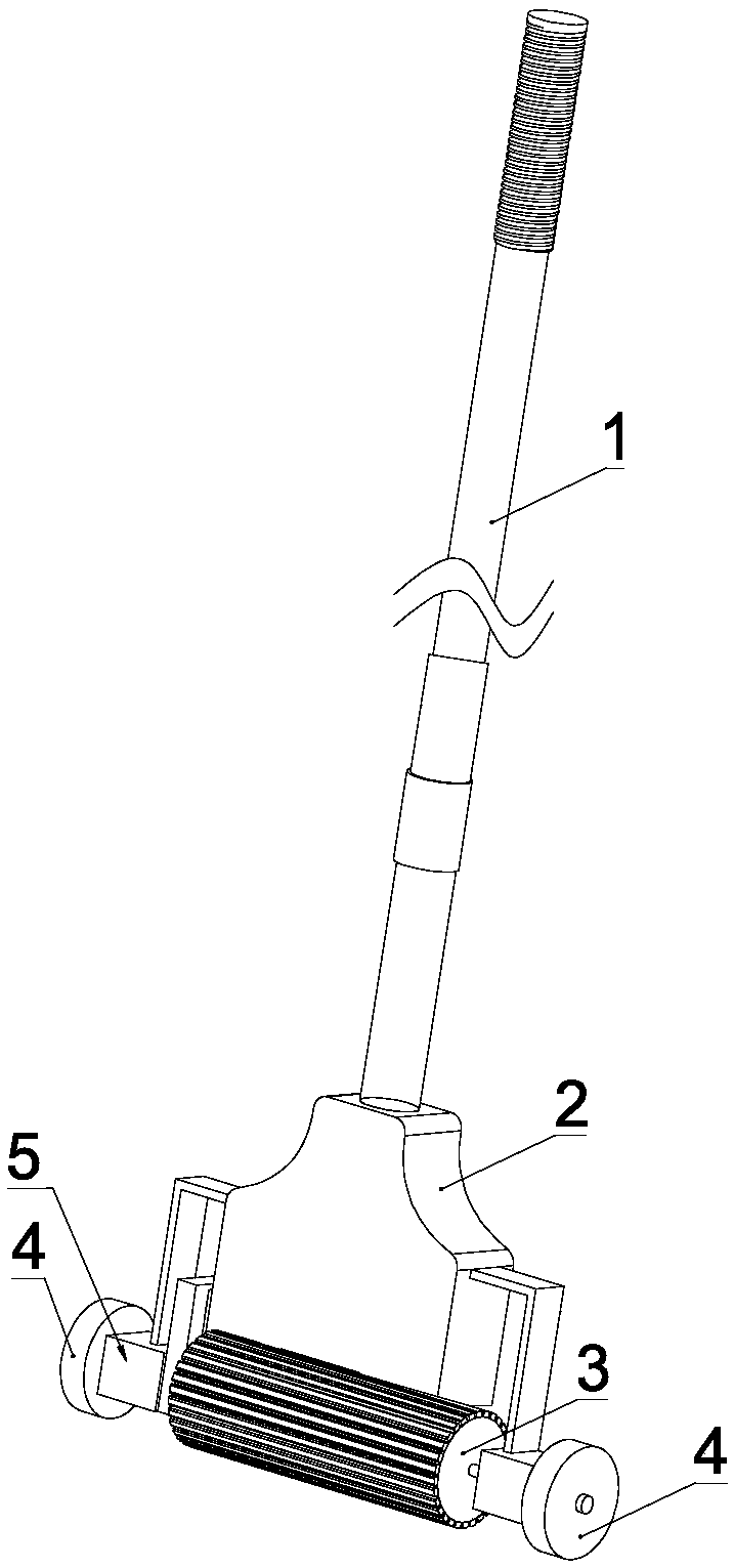
[0029] see figure 1 and figure 2 , a rolling mop of the present invention includes a handle 1, a fixed frame 2 positioned at one end of the handle 1, and a cleaning roller 3 and a walking roller 4 that are respectively rotatably connected to the fixed frame 2; wherein, the cleaning roller 3 and the walking roller 4 are connected by a differential transmission mechanism 5 for transmitting the power of the walking roller 4 to the cleaning roller 3. When the rotation direction of the cleaning roller 3 and the walking roller 4 are the same, the transmission ratio of the differential transmission mechanism 5 is greater than 1 Or less than 1, when the rotation direction of the cleaning cylinder 3 and the walking roller 4 is opposite, the transmission ratio of the differential transmission mechanism 5 is greater than 1, less than 1 or equal to 1; when mopping the floor, the walking roller 4 and the cleaning The cylinder 3 is in contact with the ground at the same time, and the fric...
Embodiment 2
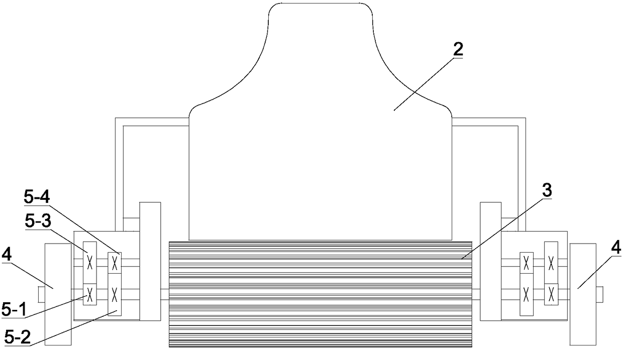
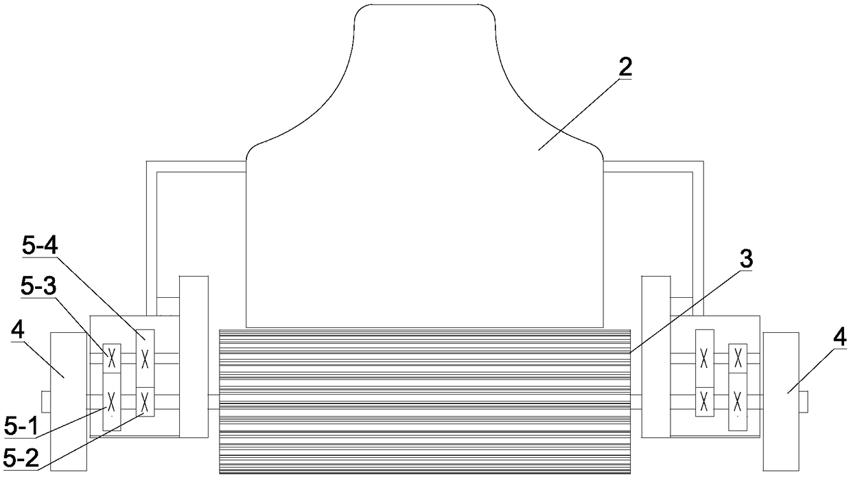
[0042] see image 3 , The difference between this embodiment and Embodiment 1 is that the first transmission gear includes a driving transmission gear 5-3 and a driven transmission gear 5-4 coaxially arranged with the main transmission gear, wherein the driving transmission gear Gear 5-3 meshes with driving gear 5-1, driven transmission gear 5-4 meshes with driven gear 5-2, and the rotation ratio between driving gear 5-1 and driving transmission gear 5-3 is greater than 1, from The rotation ratio between the driven transmission gear 5-4 and the driven gear 5-2 is greater than 1. During work, the driving gear 5-1 rotates to drive the driving gear 5-3, the driven gear 5-4, the driven gear 5-2 and the cleaning cylinder 3 to rotate in turn. The advantage of this arrangement is that under the joint action of the driving transmission gear 5-3 and the driven transmission gear 5-4, the speed change range is greatly increased, for example, the rotation ratio between the driving gear 5...
Embodiment 3
[0045] see Figure 4 , The difference between this embodiment and Embodiment 1 is that the first transmission gear is a bevel gear 5-5, the first transmission gear is rotatably connected to the fixed frame 2, the driving gear 5-1 and the driven gear 5-1 2 meshes with bevel gear 5-5 respectively. When working, the driving gear 5-1 rotates to drive the first transmission gear to rotate, and then the first transmission gear drives the rotation of the driven gear 5-2 to realize power transmission. It is worth noting that this setting can be used skillfully According to the characteristic that the bevel gear can change the power direction, after power transmission, the rotation direction of the driven gear 5-2 is opposite to that of the driving gear 5-1. In this case, no matter the transmission ratio is greater than 1, less than 1 or equal to 1. There is only sliding friction between the cleaning roller 3 and the ground. Since the sliding friction is greater than the rolling frict...
PUM
 Abstract
Description
Claims
Application Information
 - Generate Ideas
- Intellectual Property
- Life Sciences
- Materials
- Tech Scout
- Unparalleled Data Quality
- Higher Quality Content
- 60% Fewer Hallucinations
Browse by: Latest US Patents, China's latest patents, Technical Efficacy Thesaurus, Application Domain, Technology Topic, Popular Technical Reports.
© 2025 PatSnap. All rights reserved.Legal|Privacy policy|Modern Slavery Act Transparency Statement|Sitemap|About US| Contact US: help@patsnap.com