Oil-gas separation device

A separation device, oil and gas technology, applied in the field of gas-liquid separation, can solve problems such as difficulty in disassembling and assembling a cylinder cover

Pending Publication Date: 2018-09-04
SUZHOU SULLAIR GAS EQUIP
View PDF0 Cites 2 Cited by
  • Summary
  • Abstract
  • Description
  • Claims
  • Application Information

AI Technical Summary

Problems solved by technology

[0005] Therefore, the technical problem to be solved by the present invention is to overcome the problem that the oil-gas separatio

Method used


Image

  • Oil-gas separation device
  • Oil-gas separation device
  • Oil-gas separation device

Examples


Embodiment 1

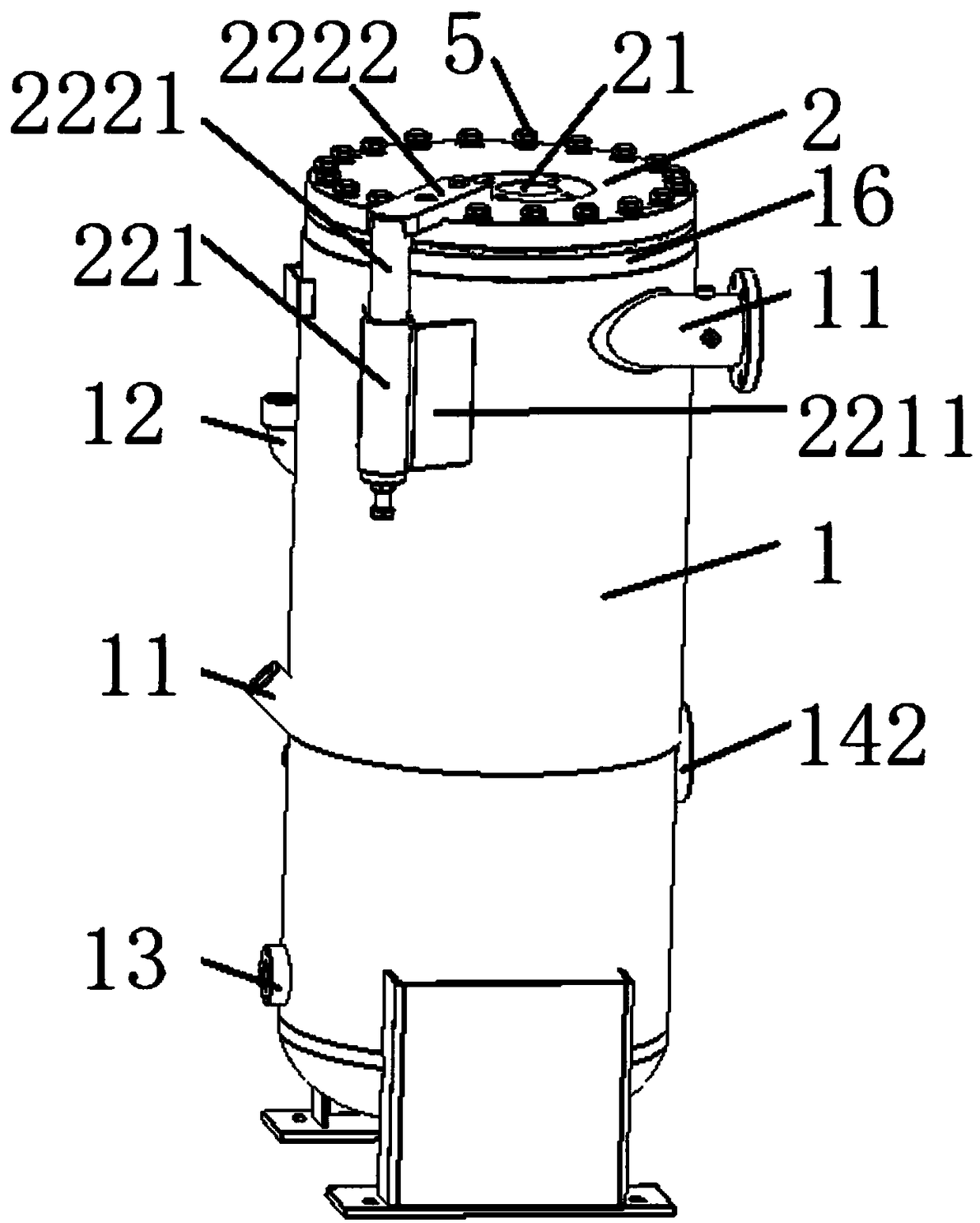
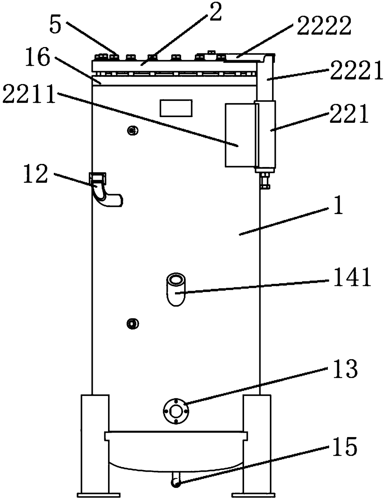
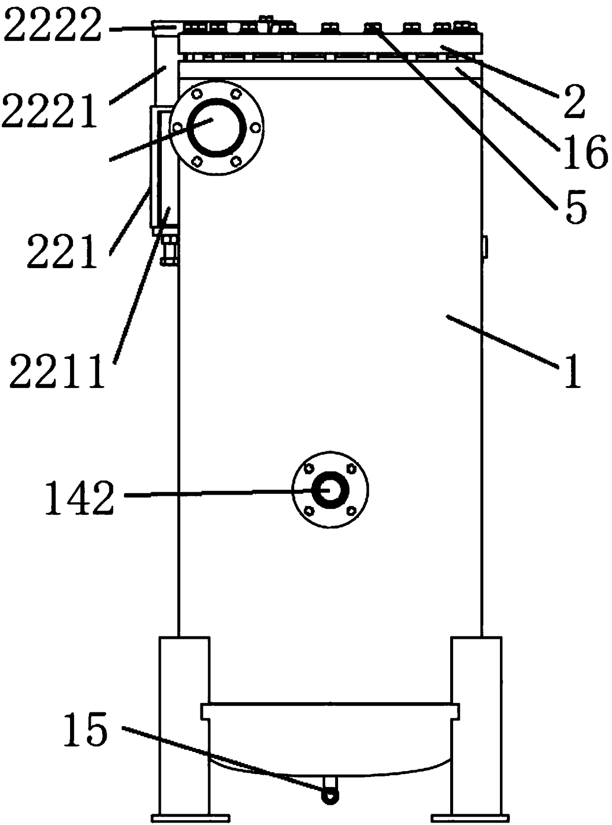
[0042] This embodiment provides an oil-gas separation device, such as Figure 1 to Figure 5 As shown, it includes: an outer cylinder 1 , a cylinder cover 2 arranged on the top of the outer cylinder 1 , an annular inner cylinder 3 connected to the outer cylinder 1 , and a plurality of spoilers 4 arranged at the lower part of the outer cylinder 1 . Specifically, the top of the outer cylinder 1 is provided with a flange 16, and the flange 16 is connected to the cylinder cover 2 through a flange and is located at the position of the flange hole through a fastener assembly 5 such as a bolt and a nut; the ring The top of the inner cylinder 3 has a protruding portion 32 protruding outward, the annular inner cylinder 3 is penetrated in the outer cylinder 1 and the protruding portion 32 abuts against the flange 16 to realize the connection between the annular inner cylinder 3 and the outer cylinder 3. Connection of cartridge 1. It should be noted that the annular inner cylinder 3 faci...


PUM


Abstract

The invention discloses an oil-gas separation device. The oil-gas separation device comprises an outer barrel and a barrel cover, wherein the outer barrel is provided with a gas inlet channel; the barrel cover is arranged at the top of the outer barrel and is provided with a gas outlet channel communicated with the inner part of the outer barrel; the barrel cover further comprises a fixed unit, wherein the fixed unit comprises a fixed part and a rotary part penetrating through the fixed part; the fixed part is connected to the outer barrel; the rotary part is connected to the barrel cover andthe rotary part does axial linear motion and rotary motion relative to the fixed part so as to move the barrel cover between a sealing position and an opening position. The fixed unit is arranged andis used for connecting the outer barrel and the barrel cover; when parts in the oil-gas separation device need to be replaced, the barrel cover can be moved between the sealing position and the opening position only if the fixed unit is operated, and the barrel cover and the outer barrel are not completely separated; compared with a condition in the prior art that the barrel cover is taken to theother place to completely separate the outer barrel and the barrel cover, the opening and closing of the barrel cover are simpler and more convenient.

Description

technical field [0001] The invention relates to the technical field of gas-liquid separation, in particular to an oil-gas separation device. Background technique [0002] The oil-gas separation device is mainly used for oil-gas separation, so that the oil-gas mixture completes the two-phase separation of oil and gas, so that there is less liquid in the gas and less gas in the liquid. Oil and gas separation devices are usually divided into vertical structure and horizontal structure according to gravity separation. However, because the horizontal structure usually occupies a large area, there are certain limitations in use. The traditional vertical structure is based on the principle of collision separation. The principle of collision separation means that the gas flow encounters an obstacle to change the flow direction and speed, so that the liquid droplets in the gas are continuously coalesced at the obstacle, and an oil film is formed due to the surface tension of the liq...

Claims


Application Information

Patent Timeline
IPC IPC(8): B01D53/24
CPCB01D53/24
Inventor 孙建朱汪刘毅
Owner SUZHOU SULLAIR GAS EQUIP
Why Eureka
Try Eureka