Sealing structure of stainless steel ventilation pipeline and production technology thereof

A sealing structure and ventilation duct technology, applied in the direction of pipes, rigid pipes, pipes/pipe joints/pipe fittings, etc., can solve the problems of vibration and sound formed by thin plates, heating in the forming area of ​​the plate surface, and wavy wrinkles on the plate surface, etc., to achieve Improve quality requirements, reduce vibration, and achieve high flatness

Pending Publication Date: 2018-09-04
江阴快力特机械有限公司
View PDF5 Cites 2 Cited by
  • Summary
  • Abstract
  • Description
  • Claims
  • Application Information

AI Technical Summary

Problems solved by technology

[0008] 1. The bite machine is generally formed by cold rolling with 5 to 9 rollers. Because the surface of the thin plate is rolled by multiple cold rolling rollers, the length direction of the bite forming area becomes shorter and shrinks, resulting in wavy wrinkles on the plate surface after the bite is formed. pleats;
[0009] 2. The biting machine passes through multiple rollers, which are continuously deformed, causing local heating in the forming area of ​​the board surface, causing wavy wrinkles on the board surface after the bite is formed;
[0010] 3. Wrinkles and waves on the surface of the board lead to changes in the diameter of the ventilation duct, as well as changes in the flow direction and speed of the wind, and, during the ventilation process, the thin board will form vibrations and noises;
[0011] 4. Especially for stainless steel, this shortcoming is greatly enlarged, and the depth of flatness waves reaches 6 to 7 millimeters, or even more than ten millimeters;
[0012] 5. This process, for ordinary plates, the maximum suitable plate thickness is 1 to 1.5 mm, and for stainless steel materials, it is suitable for plate thicknesses below 0.8 to 1 mm, that is to say, for plate thicknesses less than 0.8 mm or plate thicknesses greater than 1.5 mm, the Craft cannot be completed

Method used


Image

  • Sealing structure of stainless steel ventilation pipeline and production technology thereof
  • Sealing structure of stainless steel ventilation pipeline and production technology thereof
  • Sealing structure of stainless steel ventilation pipeline and production technology thereof

Examples


Embodiment Construction

[0059] The following will clearly and completely describe the technical solutions in the embodiments of the present invention with reference to the accompanying drawings in the embodiments of the present invention. Obviously, the described embodiments are only part of the embodiments of the invention, not all of them. Based on the embodiments of the present invention, all other embodiments obtained by persons of ordinary skill in the art without making creative efforts belong to the protection scope of the present invention.

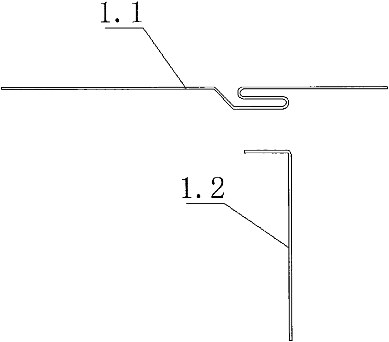
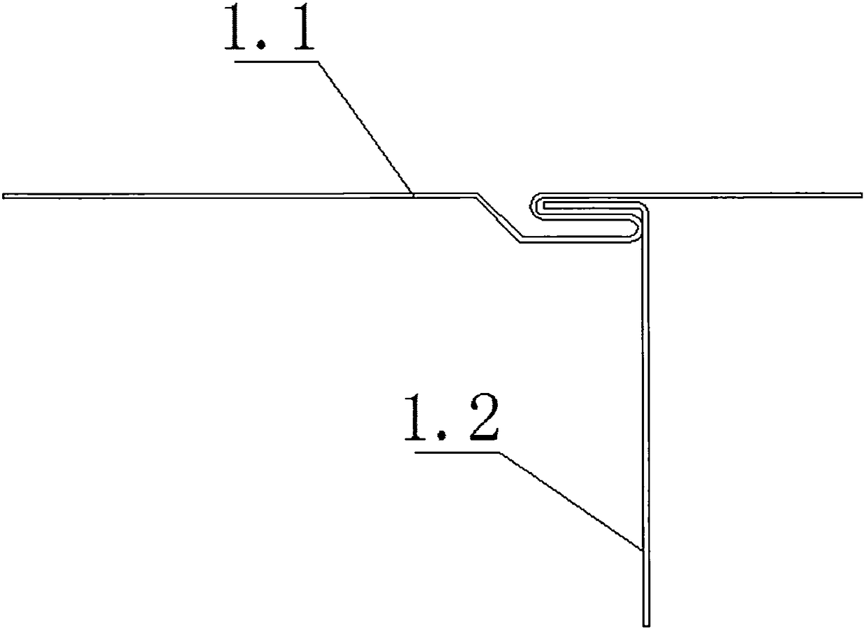
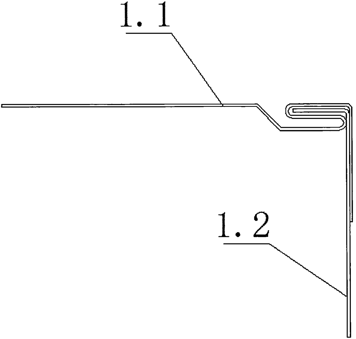
[0060] see Figure 4-Figure 11 , the present invention relates to a stainless steel ventilation duct sealing structure and its production process,

[0061] The sealing structure of the stainless steel ventilation duct includes a first stainless steel plate 2.1 and a second stainless steel plate 2.2 that are sealed and connected at the bite, and the bent second stainless steel plate 2.2 is embedded in the embedding groove of the first stainless steel plate ...


PUM


Abstract

The invention relates to a sealing structure of a stainless steel ventilation pipeline. The sealing structure of the stainless steel ventilation pipeline is characterized by comprising a first stainless steel plate (2.1) and a second stainless steel plate (2.2) which are in sealing connection through a seaming part, wherein the bent second stainless steel plate (2.2) is embedded into an embeddinggroove of the first stainless steel plate (2.1); the outer side edge of the first stainless steel plate (2.2) clings to the outer side of the outer side edge of the second stainless steel plate (2.2);and the surfaces of the first stainless steel plate (2.1) and the second stainless steel plate (2.2) are not provided with wave-shaped wrinkles, and the flatness index is less than 1mm. The sealing structure of the stainless steel ventilation pipeline and the production technology thereof have the advantages that the flatness of the spliced stainless steel ventilation pipeline is high, so that the film product quality requirement is improved.

Description

technical field [0001] The invention relates to a sealing structure of a stainless steel ventilation pipe and a production process thereof. Background technique [0002] In the film production industry, it is necessary to use the hot air blown out of the ventilation duct to dry the surface of the film. For some specific films, such as optical films, the cleanliness is very high. If the ventilation duct supported by the traditional galvanized sheet is used to Carrying out the drying operation cannot meet its special needs. [0003] Therefore, a ventilation duct made of stainless steel is developed to dry the film. In order to ensure the drying effect, the uniformity of the wind speed in the ventilation duct needs to be high, so the ventilation duct needs to have good sealing and passing performance, see Figure 1-Figure 3 , the production process of the traditional ventilation duct sealing structure is as follows: [0004] Step 1. Process the first plate 1.1 and the second p...

Claims


Application Information

Patent Timeline
Patent Type & Authority Applications(China)
IPC IPC(8): B21D21/00B21D5/01B21D1/00F16L9/02
CPCF16L9/02B21D1/00B21D5/01B21D21/00
Inventor 徐宇陆晓斌
Owner 江阴快力特机械有限公司
Why Eureka
Try Eureka