Die perforating device

A punching device, mold technology, applied in the direction of positioning device, driving device, feeding device, etc., can solve the problems of increased workload of operators, reduced work efficiency, and adhesion of burrs and debris

Inactive Publication Date: 2018-09-04
宋君能
View PDF5 Cites 2 Cited by
  • Summary
  • Abstract
  • Description
  • Claims
  • Application Information

AI Technical Summary

Problems solved by technology

Wherein some parts need to punch several holes through the parts. In the prior art, the required hole is first searched for a position, and then the parts are artificially rotated to carry out the punching operation of the remaining

Method used


Image

  • Die perforating device
  • Die perforating device

Examples


Embodiment Construction

[0014] The present invention will be described in further detail below by means of specific embodiments:

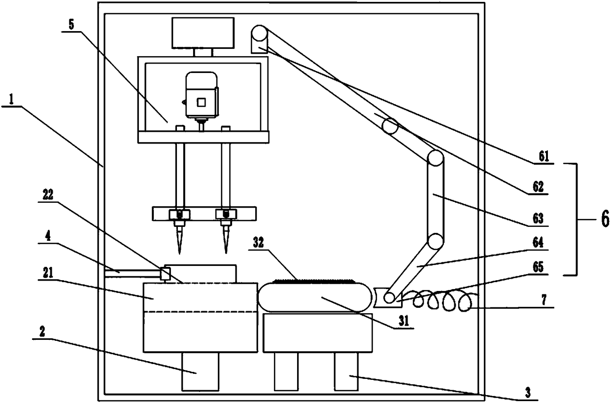
[0015] The reference signs in the drawings of the description include: frame 1, first base 2, cavity 21, opening 22, second base 3, push plate 31, frosted layer 32, clamping mechanism 4, punching device 5, ring Track 51, slide block 511, second motor 512, punching head 513, vertical rod 514, disc 52, slide bar 521, push block 522, first motor 53, linkage mechanism 6, first connecting rod 61, The second connecting rod 62, the third connecting rod 63, the push rod 64, the push block 65, the elastic member 7, the fixed plate 8, and the hydraulic cylinder 9.

[0016] The embodiment is basically as attached figure 1 - attached figure 2 Shown: a punching device for a mold, including a frame 1, a first base 2 and a second base 3 are arranged in the frame 1, a push plate 31 is slidably connected to the second base 3, and the push plate 31 is detachable A frosted layer 32 is c...


PUM


Abstract

The invention relates to the field of die equipment, in particular to a die perforating device comprising a machine frame. A first base and a second base are arranged in the machine frame. A pushing plate is connected to the second base in a sliding manner. An abrasive layer is connected to the pushing plate. The first base is provided with a cavity containing the pushing plate. The cavity is provided with an opening. The machine frame is provided with perforating equipment. A connection rod mechanism is installed on the upper side of the perforating equipment. The tail end of the connection rod mechanism is arranged on one side of the pushing plate. An elastic piece is connected between the tail end of the connection rod mechanism and the machine frame. According to the die perforating device, the pushing plate is arranged on the second base, the pushing plate is provided with the abrasive layer, the cavity used for containing the pushing plate is arranged in the first base, in this way, remaining chips and burrs, existing after perforating is completed, of the bottom of the die are removed, and a die part is perforated through the perforating equipment.

Description

technical field [0001] The invention relates to the field of mold equipment, in particular to a punching device for a mold. Background technique [0002] Mold, various molds and tools used in industrial production for injection molding, blow molding, extrusion, die-casting or forging forming, smelting, stamping and other methods to obtain the required products. In short, a mold is a tool used to make shaped objects. This tool is composed of various parts, and different molds are composed of different parts. Wherein some parts need to punch several holes through the parts. In the prior art, the required hole is first searched for a position, and then the parts are artificially rotated to carry out the punching operation of the remaining holes, which undoubtedly increases the workload of the operator. large, reducing work efficiency. And after the punching operation is completed, there will be burrs and debris attached to the outer surface of the bottom of the part. [0003...

Claims


Application Information

Patent Timeline
IPC IPC(8): B23B41/00B23B47/06B23B47/22B23Q3/06B23Q5/10B23Q5/26B23Q11/00
CPCB23B41/00B23Q3/06B23Q5/10B23Q5/26B23Q11/0042
Inventor 宋君能
Owner 宋君能
Why Eureka
Try Eureka