Grinding machine

A technology for grinding machines and pulleys, which is applied in the direction of grinding machines, grinding beds, and parts of grinding machine tools, and can solve problems such as low efficiency

Pending Publication Date: 2018-09-04
CHANGSHA AERONAUTICAL VACATIONAL AND TECHNICAL COLLEGE +1
View PDF6 Cites 6 Cited by
  • Summary
  • Abstract
  • Description
  • Claims
  • Application Information

AI Technical Summary

Problems solved by technology

For workpieces, shaft parts are widely used in production and life, such as rotary shafts and drill bits, etc. In order to facilitate assembly and use, these shaft parts are often chamfered at both ends. The existing chamfer The angle process is to clamp the shaft parts on the lathe, and use the turning tool to chamfer them; there are also some shaft parts that need to have a guiding function, and their end faces need to be processed into a conical shape. The existing processing technology also uses Turning processing, although turning processing can meet the processing requirements, but turning processing can only process one end of one shaft part in one clamping, which is inefficient

Method used


Image

  • Grinding machine
  • Grinding machine
  • Grinding machine

Examples


Embodiment Construction

[0033] The present invention will be described in further detail below in conjunction with the accompanying drawings and specific embodiments.

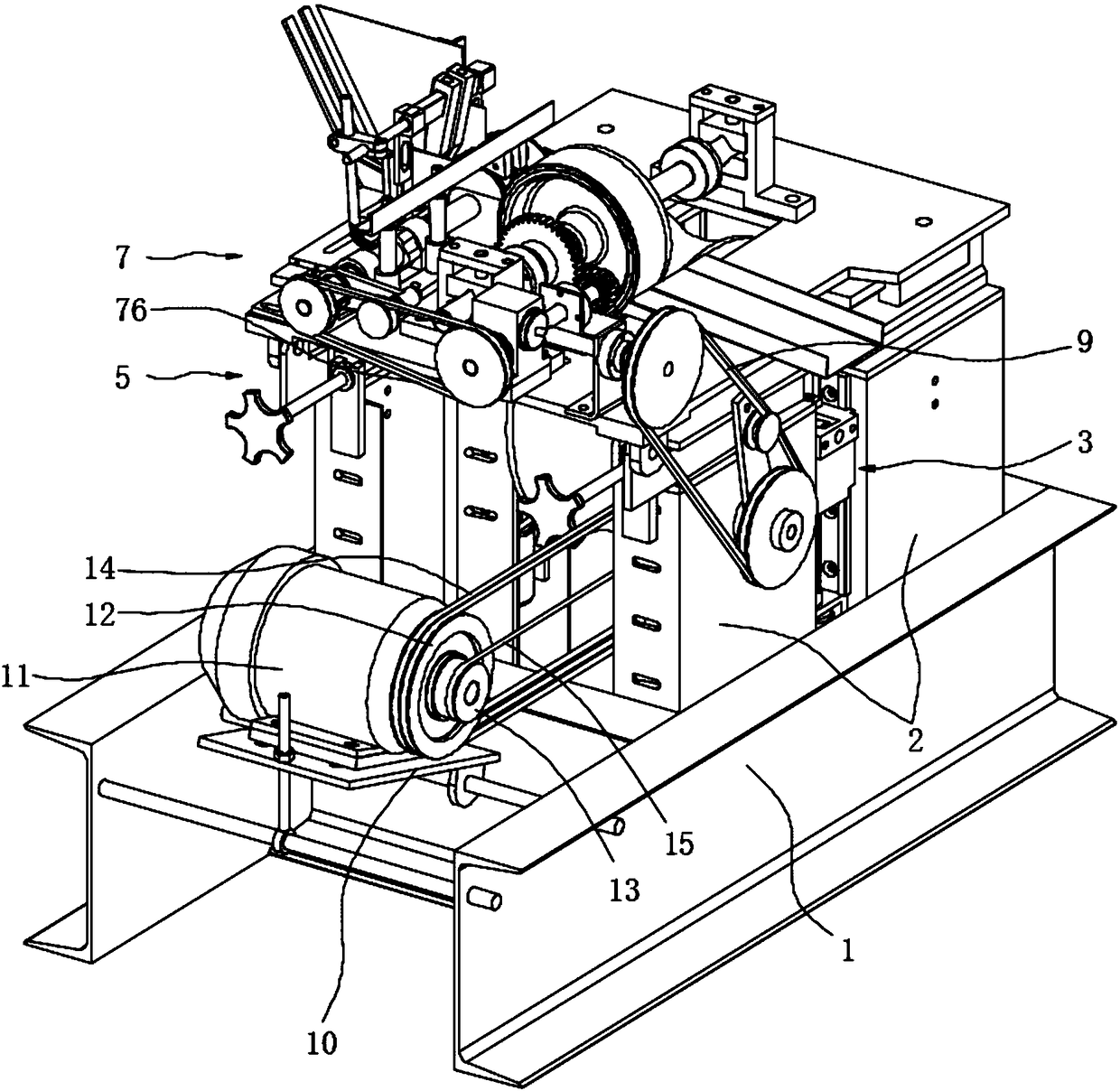
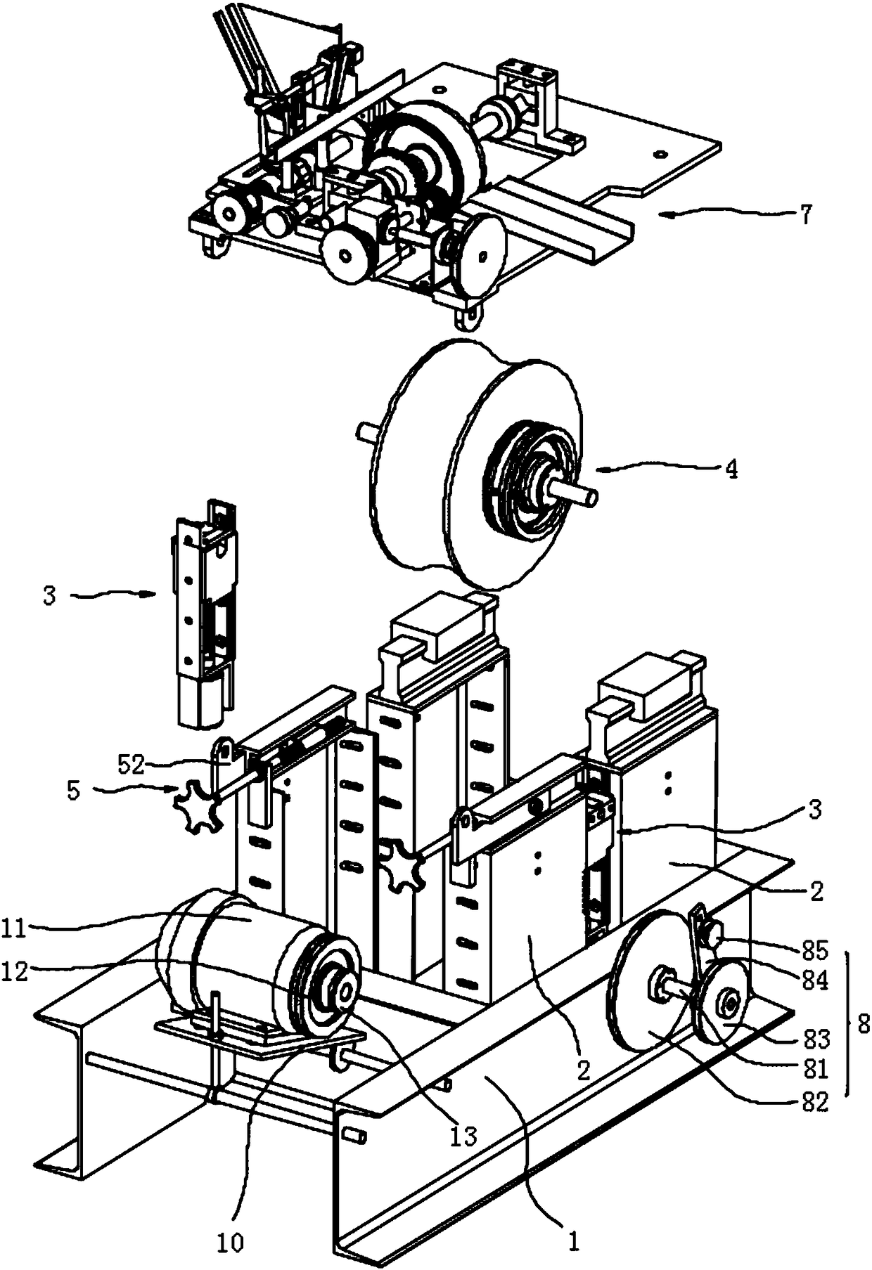
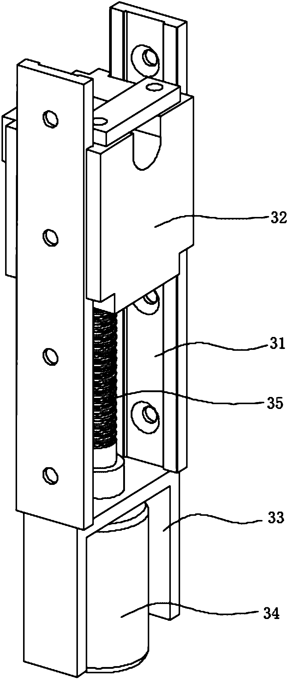
[0034] Such as Figure 1 to Figure 2 Shown: a kind of grinder, comprises frame 1, is respectively provided with a group of brackets 2 on the front side and rear side of frame 1, each group of brackets 2 comprises two support plates vertically arranged, on the two supports of each group of brackets 2 A group of lifting devices 3 are respectively arranged between the plates, and the lifting device 3 includes a slide rail 31, a slide block 32, a servo motor support 33, a servo motor 34, a lifting screw 35 and a lifting nut (not shown), and the slide rail 31 is vertical Set on the bracket 2, that is, slide rails 31 are respectively arranged on the two support plates of each group of brackets, the slider 32 is slidably arranged on the slide rail 31, the lifting nut is fixed on the bottom end of the slider 32, and the servo motor bracket 33...


PUM


Abstract

The invention provides a grinding machine. The grinding machine comprises a machine frame, wherein supports are arranged on the machine frame, lifting devices are arranged on the supports, and grinding wheel fastening devices are arranged on the lifting devices; feeding devices are arranged above the supports, feeding base plates are arranged on the feeding devices, and automatic feeding devices are arranged on the feeding base plates; a driving motor is arranged on the machine frame, the driving motor provides power for the grinding wheel fastening devices and the automatic feeding devices simultaneously, after shaft parts enters a material clamping and conveying device after passing through the feeding devices, the material clamping and conveying device enables the shaft parts to rotateto be in contact with the grinding wheel fastening devices which rotate at high speed; and the feeding amount is adjusted through the feeding devices and the lifting devices, so that chamfering or grinding the conical surfaces of the shaft parts can be carried out according to requirements, the shaft parts can be machined continuously in batches, and the production efficiency can be greatly improved.

Description

technical field [0001] The invention relates to the field of mechanical processing equipment, in particular to a grinding machine. Background technique [0002] Grinding machines are machine tools that use abrasive tools to grind workpieces. Most grinding machines use high-speed rotating grinding wheels to grind workpieces. Grinding machines can be mainly divided into surface grinders, internal and external cylindrical grinders, etc. according to types. Surface grinders are grinders used to grind the plane of workpieces; For workpieces, in production and daily life, shaft parts are widely used, such as rotating shafts and drill bits, etc. In order to facilitate assembly and use, these shaft parts are often chamfered at both ends. The existing chamfer The angle process is to clamp the shaft parts on the lathe, and use the turning tool to chamfer them; there are also some shaft parts that need to have a guiding function, and their end faces need to be processed into a conical...

Claims


Application Information

Patent Timeline
Patent Type & Authority Applications(China)
IPC IPC(8): B24B9/02B24B19/09B24B41/00B24B41/02B24B41/06B24B47/20
CPCB24B9/02B24B19/09B24B41/00B24B41/005B24B41/02B24B41/067B24B47/20
Inventor 吴云锋陈洁盛科洪晓东
Owner CHANGSHA AERONAUTICAL VACATIONAL AND TECHNICAL COLLEGE
Why Eureka
Try Eureka