Horizontal supercutical fluid foaming equipment

A technology of supercritical fluid and foaming equipment, which is applied in the field of polymer material processing, can solve the problems of inconvenient operation of a supercritical fluid reactor, a safety protection device, etc. Effect

Active Publication Date: 2018-09-04
JIANGSU DAMAONIU NEW MATERIAL TECH CO LTD
View PDF7 Cites 6 Cited by
  • Summary
  • Abstract
  • Description
  • Claims
  • Application Information

AI Technical Summary

Problems solved by technology

[0006] Aiming at the problems of inconvenient operation and insufficient safety protection devices in the s

Method used


Image

  • Horizontal supercutical fluid foaming equipment
  • Horizontal supercutical fluid foaming equipment
  • Horizontal supercutical fluid foaming equipment

Examples


Example Embodiment

[0028] Example 1 Tank Closure Process

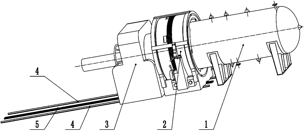
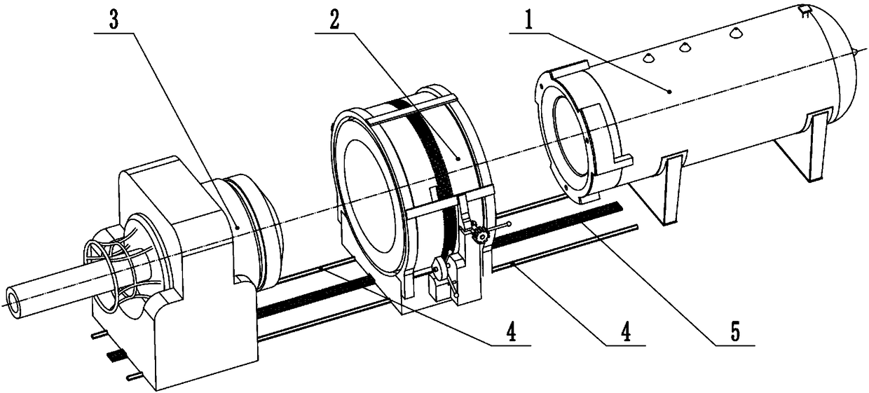
[0029] Refer to the attached figure 1 to the attached Figure 8 , when the tank assembly (1), the clamp assembly (2), and the compression assembly (3) are in a non-combined state, put the polymer to be processed into the inner cylinder (15), and then pass the clamp The rotation control assembly (43) in the assembly (2) rotates the clamp (45), and the steps are as follows:

[0030] 1) Rotate the limit handle (64) until the handle is in contact with the limit pin B (78). At this time, the notch of the notch disc (79) of the limit handle (64) is facing the clamp (45), which does not affect the clamp (45) Rotation;

[0031] 2) Rotate the gear handle (62) installed on the rotating shaft (63) around the axis A (74), so that the gear handle (62) is rotated into the shaft limit groove (76) of the base B (61). The gear of the gear handle (62) meshes with the rotating teeth (86) on the clamp (45), and the clamp (45) can be rotated by rotating ...

Example Embodiment

[0036] Embodiment 2 supercritical fluid processing process

[0037] Refer to the attached figure 1 , attached image 3 , attached Figure 7 and attached Figure 8 , the preparation steps for supercritical fluid processing:

[0038] 1) Heating medium oil injection, emptying and cleaning

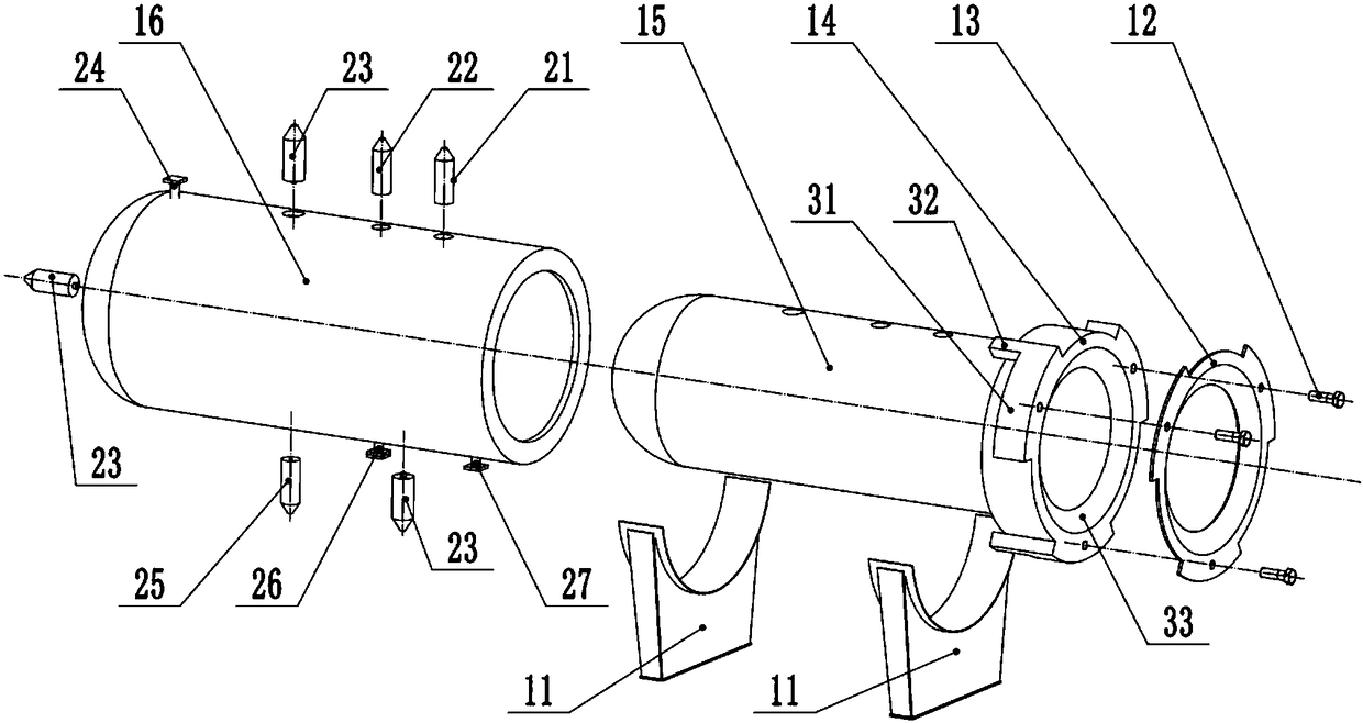
[0039] Inject the oil from the heat transfer oil inlet (27) into the hollow space formed by the tank body locking end (14), the inner cylinder (15) and the jacket (16), and the excess oil will be discharged from the heat transfer oil outlet (24) For recycling, when the oil contains impurities and needs to be discharged from the tank body, the oil can be completely emptied by connecting an external conduit at the sewage outlet (26).

[0040] 2) Installation and connection of tank monitoring, safety devices and external media

[0041] Install and connect the safety valve, pressure gauge and temperature sensor at the safety valve interface (21), the pressure gauge interface (22) and the tem...

Example Embodiment

[0043] Embodiment 3 Tank opening process

[0044] Refer to the attached figure 2 to the attached Figure 8 , the steps of the tank opening process are:

[0045] 1) Rotate the circular turntable (96) to unscrew the T-shaped pressing block (93) of the pressing assembly (3) from the clamp (45), and then unscrew the pressing assembly (3) along the track (4) as a whole Move outward until the tapered guide rod (91) is out of contact with the clamp (45);

[0046] 2) Rotate the limit handle (64) until the handle is in contact with the limit pin B (78). At this time, the notch of the notch disc (79) of the limit handle (64) is facing the clamp (45), and the clamp (45) In the unlocked state, then the gear of the gear handle (62) is engaged with the rotating teeth (86) on the clamp (45), and the clamp (45) can be rotated by rotating the gear handle (62);

[0047] 3) Turn the clamp (45) in the opposite direction to make the guide limit groove (85) turn to the position of the notch di...


PUM


Abstract

Aiming at the problems that a conventional supercutical fluid reaction kettle is inconvenient to operate and security protection devices are insufficient, the invention discloses horizontal supercutical fluid foaming equipment which mainly consists of a tank component, a hoop component, a pressing component, a track and a rack, wherein the tank component is horizontally arranged; the whole tank component is sealed in a hooped manner; the hoop component and the pressing component are matched with the track and the rack and are arranged with the tank component in a linear manner; the hoop component and the pressing component are moved in a track direction; and the hoop component is matched with the end part of the tank component through guide of the track; the pressing component is mounted in the hoop component along guide of the track. By adopting the equipment, the track is adopted for horizontal movement matching, a tank is locked by using a dual structure, and the operation of the device is facilitated; and the tank is provided with pressure, temperature and security protection devices and gas recycling device mounting interfaces, and real-time monitoring and security protectionin the processing process can be achieved. The equipment is applicable to supercutical fluid on-batch production processing on polymer granules.

Description

technical field [0001] The invention relates to the field of polymer material processing, mainly to supercritical processing of foamed materials, and in particular to a horizontal supercritical fluid foaming device. Background technique [0002] Polymer supercritical fluid foaming methods mainly include continuous extrusion foaming, injection foaming and intermittent kettle foaming. Different molding methods have different characteristics. Continuous extrusion molding is suitable for foamed materials with regular cross-sectional shapes. Injection foam molding can inject foamed products with complex shapes. These two molding processes have high efficiency, but the equipment investment is large and the process It is cumbersome; although intermittent kettle foaming is less efficient than the former two, the product quality is stable, and it is the most widely used in experimental research. Since polymer supercritical foaming requires certain conditions such as temperature and ...

Claims


Application Information

Patent Timeline
IPC IPC(8): B29C44/34B29C44/60
CPCB29C44/3442B29C44/35B29C44/60
Inventor 张振秀温时宝
Owner JIANGSU DAMAONIU NEW MATERIAL TECH CO LTD
Why Eureka
Try Eureka