
Zone control system for temperature in carriage and zone temperature-adjusting method

A technology for temperature partitioning and control systems, which is applied to railway car body parts, railway vehicle heating/cooling, transportation and packaging, etc. Dissatisfaction among young people and other issues, to achieve the effect of pleasant environment in the car, simple structure and low manufacturing cost

Inactive Publication Date: 2018-09-04
CRRC QINGDAO SIFANG CO LTD
View PDF6 Cites 14 Cited by
  • Summary
  • Abstract
  • Description
  • Claims
  • Application Information

AI Technical Summary

Problems solved by technology

[0002] The existing rail vehicles are generally equipped with air-conditioning devices, and the air from the air-conditioning is evenly sent to the compartment through the air duct, and the air volume of each air outlet is basically the same, so that the temperature in the compartment is uniform. The number of passengers is large, and different people in the compartment have different temperature requirements. If the compartment temperature is constant, some people may feel very cold, while others may feel very hot, especially the elderly and children in the compartment. Sensitive, if the temperature of the compartment is too cold, it is easy to cause a cold, and if the temperature of the compartment is too hot, it will often cause dissatisfaction among the young people, so it is difficult to meet the comfort requirements of passengers. Similarly, the existing long-distance passenger cars and some buses Air conditioners are also installed, and the passengers in the bus also have individual requirements for the temperature inside the car. Among them, some long-distance buses have air-conditioning ports that can be adjusted manually, but the air-conditioning system of the bus can only know the overall temperature in the car. The temperature cannot be matched to the optimal operating mode according to the usage of the air-conditioning outlet in the car, so the temperature adjustment effect is limited and the level of intelligence is low

Method used


Image

  • Zone control system for temperature in carriage and zone temperature-adjusting method
  • Zone control system for temperature in carriage and zone temperature-adjusting method
  • Zone control system for temperature in carriage and zone temperature-adjusting method

Examples


Embodiment 1

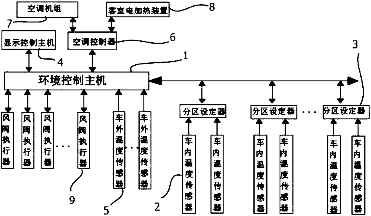
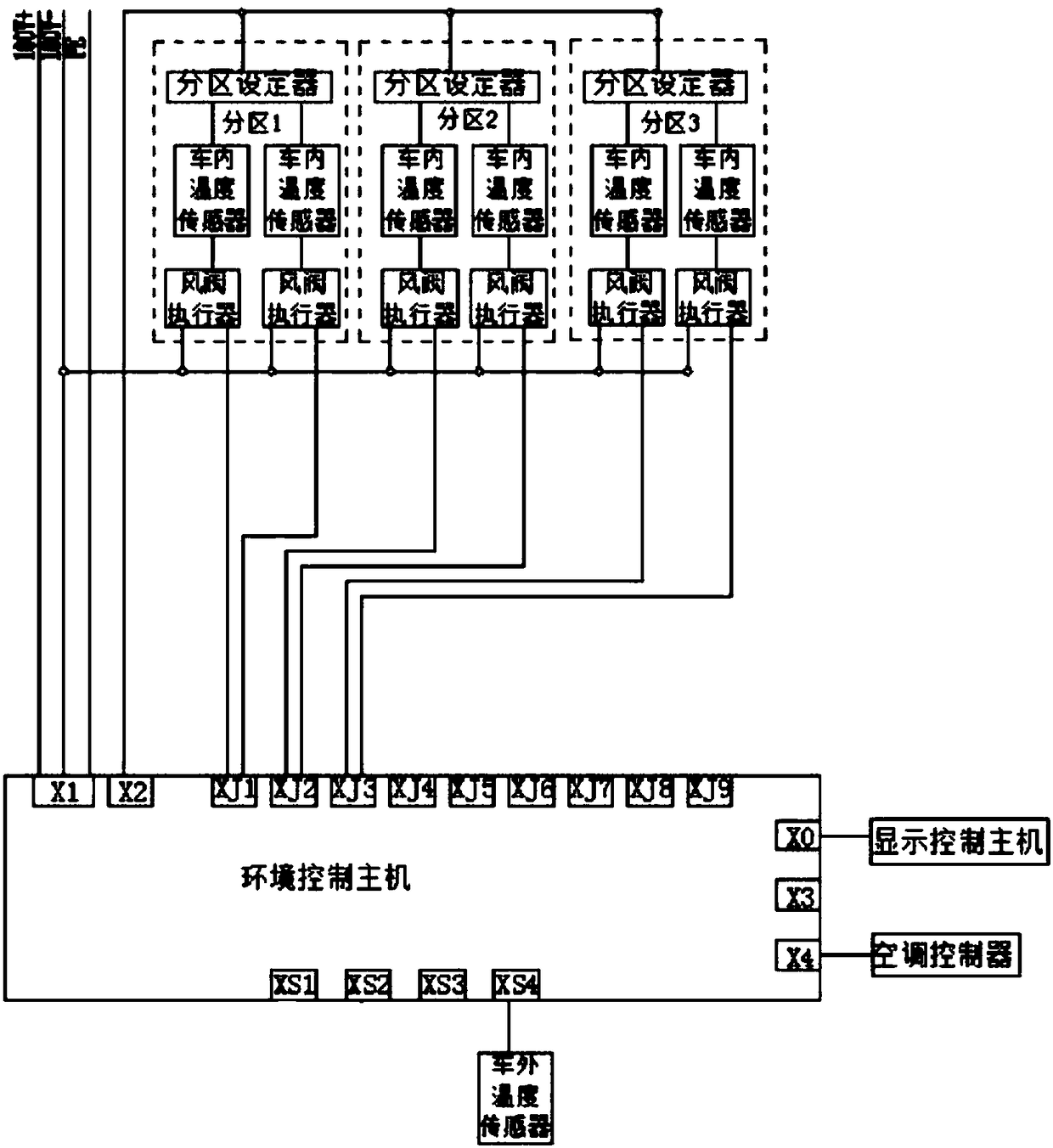
[0036] Such as figure 1 with figure 2 As shown, a compartment temperature zone control system includes an air conditioning system, an environment control host 1 , an interior temperature sensor 2 , a zone setter 3 , a display control host 4 and an outside temperature sensor 5 . The inside of the compartment is divided into a plurality of partitions, and at least one interior temperature sensor 2 and a partition setting device 3 are installed in each partition, and at least one air-conditioning outlet is provided in each partition. The environmental control host 1 is connected to the air-conditioning system in the car, and is used to send control commands to the air-conditioning system, and has a power interface and a plurality of communication interfaces, wherein the power interface is connected to the power supply system in the car, and the communication interface is connected to the communication interface in the car. Internet connection. The partition setter 3, the displ...

Embodiment 2

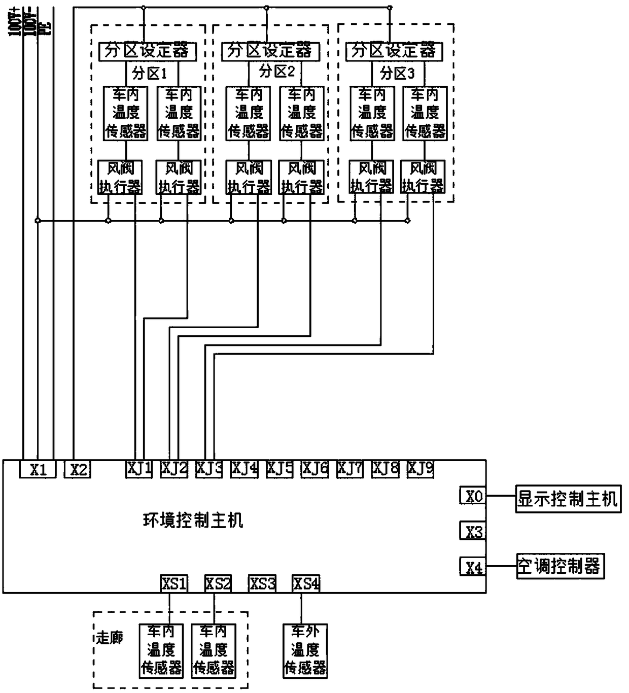
[0045] Such as image 3 As shown, the difference between the present embodiment and the first embodiment is that, on the basis of the first embodiment, the present embodiment is also provided with an in-vehicle temperature sensor 2 in the corridor of the carriage, and is connected with the environment control host 1, and the environment The control host 1 obtains the current temperature in each zone and corridor for weighting calculation.

Embodiment 3

[0047] Such as Figure 4 As shown, the difference between this embodiment and Embodiment 1 is that a plurality of humidity sensors 10 and a humidifying device 11 connected to the environment control host 1 are added in the compartment of this embodiment, and the humidity sensor 10 is configured to detect humidity in the compartment. The current humidity of each zone, and the detection results are transmitted to the environment control host 1, so that the environment control host 1 can obtain the current humidity information of each zone; the humidifier 11 is connected with the air outlet of the air conditioner, and is controlled by the environment control host 1 . The humidity sensor 10 and the temperature sensor 2 in the car can be integrated together and connected with the zone setter 3. The zone setter 3 can display the current humidity information of the zone where it is located. When the humidity in the compartment is low, the environment control host 1. Control the oper...


PUM


Abstract

The invention relates to a zone control system for the temperature in a carriage. The zone control system for the temperature in the carriage comprises an air conditioner system, and further comprisesan environment control host, a plurality of in-vehicle temperature sensors and a plurality of zone setters, wherein the environment control host is connected with the air conditioner system in the carriage, and is used for transmitting control commands for the air conditioner system; the in-vehicle temperature sensors are configured to detect current temperatures of various zones in the carriageand transmit detection results to the environment control host; the zone setters are correspondingly arranged in the various zones, are connected with the environment control host through a communication network, and are configured to set or adjust the set temperatures of the zones in which the zone setters are located; and the environment control host adjusts running of the air conditioner systemaccording to the set temperatures, and enables the temperatures of the various zones of the carriage to reach or be close to the set temperatures. The invention further relates to a zone temperature-adjusting method using the zone control system for the temperature in the carriage. The carriage is divided into a plurality of zones, and the temperature of each zone is adjusted independently to meet demands of users.

Description

technical field [0001] The invention relates to a temperature control system, in particular to a compartmentalized temperature control system and a compartmentalized temperature adjustment method. Background technique [0002] The existing rail vehicles are generally equipped with air-conditioning devices, and the air from the air-conditioning is evenly sent to the compartment through the air duct, and the air volume of each air outlet is basically the same, so that the temperature in the compartment is uniform. The number of passengers is large, and different people in the compartment have different temperature requirements. If the compartment temperature is constant, some people may feel very cold, while others may feel very hot, especially the elderly and children in the compartment. Sensitive, if the temperature of the compartment is too cold, it is easy to cause a cold, and if the temperature of the compartment is too hot, it will often cause dissatisfaction among the y...

Claims


Application Information

Patent Timeline
Patent Type & Authority Applications(China)
IPC IPC(8): B61D27/00
CPCB61D27/00
Inventor 蒲栋李树典刘振环刘永刚姜皓沥
Owner CRRC QINGDAO SIFANG CO LTD
Learn More