Automatic temperature control power chip structure and preparation method thereof

A power chip and temperature control technology, applied in the fields of semiconductor/solid-state device manufacturing, electrical components, electrical solid-state devices, etc., can solve the problems of affecting thermal fatigue life, reducing the reliability of high-power devices, and hindering the heat dissipation performance of high-power devices, etc. Achieve precise control of temperature uniformity, enhanced direct heat dissipation and heat dissipation

Active Publication Date: 2022-04-12
合肥阿基米德电子科技有限公司
View PDF4 Cites 0 Cited by
  • Summary
  • Abstract
  • Description
  • Claims
  • Application Information

AI Technical Summary

Problems solved by technology

At present, thermal interface materials commonly used in commercial use have relatively low thermal conductivity and relatively large thermal resistance, which seriously hinders the heat dissipation performance of high-power devices, thereby reducing the reliability of high-power devices and affecting the thermal fatigue life.
Therefore, the heat dissipation of high-power devices still needs to be optimized

Method used


Image

  • Automatic temperature control power chip structure and preparation method thereof
  • Automatic temperature control power chip structure and preparation method thereof
  • Automatic temperature control power chip structure and preparation method thereof

Examples


preparation example Construction

[0058] Corresponding to a kind of automatic temperature control power chip structure, the present invention provides a kind of automatic temperature control power chip preparation method, such as Figure 8 Shown, preparation method comprises:

[0059] Step S1, preparing the N-P-N layer of the IGBT;

[0060] Step S2, using the N region of the N-P-N layer as the substrate to perform epitaxial growth to form a plurality of N-type epitaxial layers;

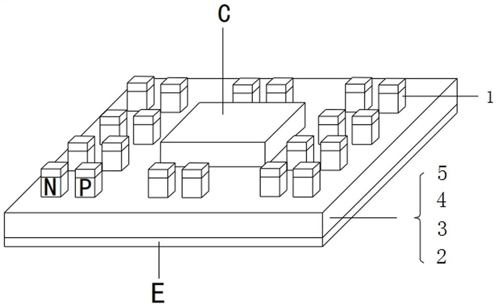
[0061] Step S3, etching the plurality of N-type epitaxial layers through a metal mask to form an arrayed columnar structure;

[0062] Step S4, directionally injecting P-type impurity ions into each columnar structure in the arrayed columnar structure to form an arrayed P-N thermocouple structure 1;

[0063] Step S5, performing metallization on the arrayed P-N thermocouple structure 1 and the P+ drain injection region 5 in the N-P-N layer by evaporation or sputtering to form the metal layer of the IGBT.

Embodiment 1

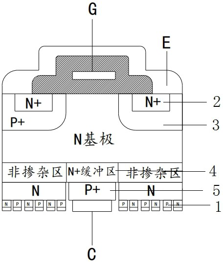
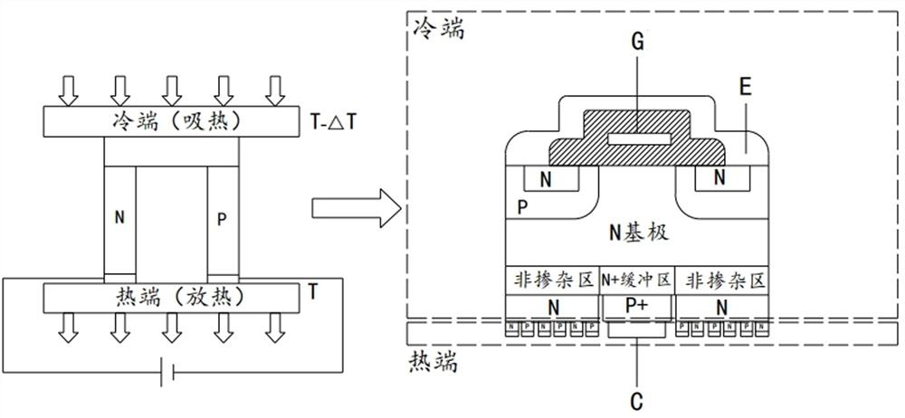
[0065] The IGBT is an asymmetric IGBT (also known as a punch-through IGBT) with an N+ buffer zone 4 . Asymmetric IGBT has the advantages of small forward voltage drop, short turn-off time, and small tail current when turned off, but its reverse blocking ability is relatively weak.

[0066] refer to Figure 4 , Insulated gate bipolar transistor includes: gate, emitter, collector, gate region arranged in sequence from emitter to collector, N+ source region 2, P-type region 3, N base, N+ buffer zone 4 and P+ Drain into region 5. A gate is attached to the gate region. One side of the multiple N-type epitaxial layers is connected to the N+ buffer zone 4 , and the other side of the multiple N-type epitaxial layers is provided with an arrayed P-N thermocouple structure 1 .

[0067] Among them, the N+ region attached to the emitter (E) is the source region, the P+ region is the P-type region 3, the N+ region attached to the P+ region is the N buffer zone, the control region of the ...

Embodiment 2

[0080] The IGBT is a symmetrical IGBT (also known as a non-punch-through IGBT), without an N+ buffer zone 4. Non-punch-through IGBT means that the electric field does not penetrate the N-drift region. The basic technical principle of NPT (Non-PunchThrough, non-punch-through) is to cancel the N+ buffer zone and directly inject space charge into the collector region to form a high-resistance region. The main confluence of the holes is replaced by a P+ collector. The symmetrical IGBT has strong forward and reverse blocking ability, and its other characteristics are worse than those of the punch-through IGBT.

[0081] refer to Figure 5 , The insulated gate bipolar transistor includes: a gate, an emitter, a collector, a gate region arranged sequentially from the emitter to the collector, an N+ source region 2 , a P-type region 3 , an N base and a P+ drain injection region 5 . A gate is attached to the gate region. One side of the multiple N-type epitaxial layers is connected to...


PUM


Abstract

The invention relates to an automatic temperature control power chip structure and a preparation method thereof, and belongs to the technical field of power electronic device packaging, an array type P-N thermocouple structure is formed on the bottom surface of an insulated gate bipolar transistor through directional doping by utilizing a semiconductor Peltier effect, and a reverse voltage is applied to the array type P-N thermocouple structure, so that the temperature of the insulated gate bipolar transistor is automatically controlled. When direct current is introduced into the thermocouple, heat absorption and heat release reactions are generated at the junction of the thermocouple according to different introduction directions of the direct current. And meanwhile, due to the array structure, the temperature uniformity of the chip can be accurately controlled, the partitioned temperature control of the chip is realized, and the direct heat dissipation and soaking capability of the chip is enhanced.

Description

technical field [0001] The invention relates to the technical field of packaging of power electronic devices, in particular to an automatic temperature control power chip structure and a preparation method. Background technique [0002] IGBT (Insulated Gate Bipolar Transistor), also known as insulated gate bipolar transistor, is widely used in industry, 4C (communication, computer, consumer electronics, automotive electronics), home appliances and other industrial fields as the core semiconductor device for weak current control and strong current. [0003] With the rapid development of integrated circuit technology, the stacked structure of power devices is relatively complex, the thermal resistance chain is long, and the heat dissipation and heat soaking problems of power chips are particularly prominent. At present, the commonly used heat dissipation method in the industry is still device / module + thermal interface material (ThermalInterfacial Materials, TIM) + heat sink (...

Claims


Application Information

Patent Timeline
Patent Type & Authority Applications(China)
IPC IPC(8): H01L23/38H01L29/739H01L21/331
Inventor 周洋马坤宋一凡孙亚萌
Owner 合肥阿基米德电子科技有限公司
Why Eureka
Try Eureka