

Pneumatic conveying feeding device`
A feeding device and pneumatic conveying technology, which is applied in the direction of conveying bulk materials, conveyors, transportation and packaging, etc., can solve the problems of air flow backflow at the feeding port, complicated cleaning and unclogging operations, and blockage of the feeding device. Achieve the effect of solving pipeline blockage, improving carrying capacity and ensuring smoothness
- Summary
- Abstract
- Description
- Claims
- Application Information
AI Technical Summary
Problems solved by technology
Method used
Image

Examples
Embodiment 1
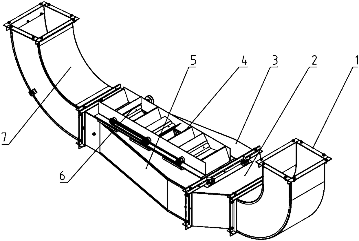
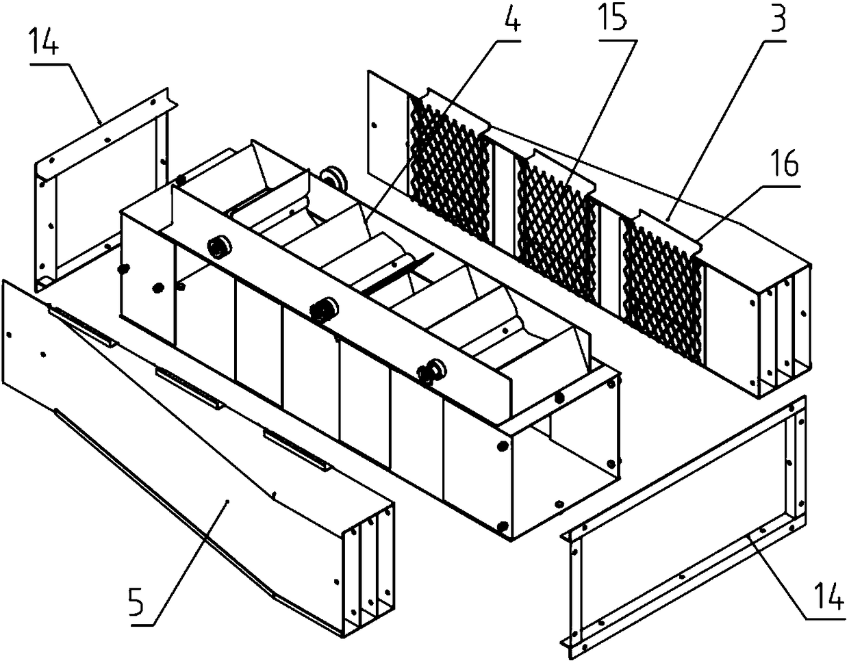
[0029] This embodiment is a pneumatic conveying feeding device matched with a full-feeding peanut picking combine harvester, and its basic structure is as follows: figure 1 As shown: the outlet of the air inlet pipe 1 connected to the air inlet of the fan outside the air inlet is respectively connected with the inlet ends of the left and right air guide pipes 5 and 3 and the middle blanking pipe 4 through the diversion control device 2, and the left and right air guide pipes 5 The inner sides of , 3 communicate with both sides of the middle drop pipe 4 through grid plate 15 respectively (referring to image 3 ), the outlet end of the middle drop pipe 4 communicates with the feed pipe 7.
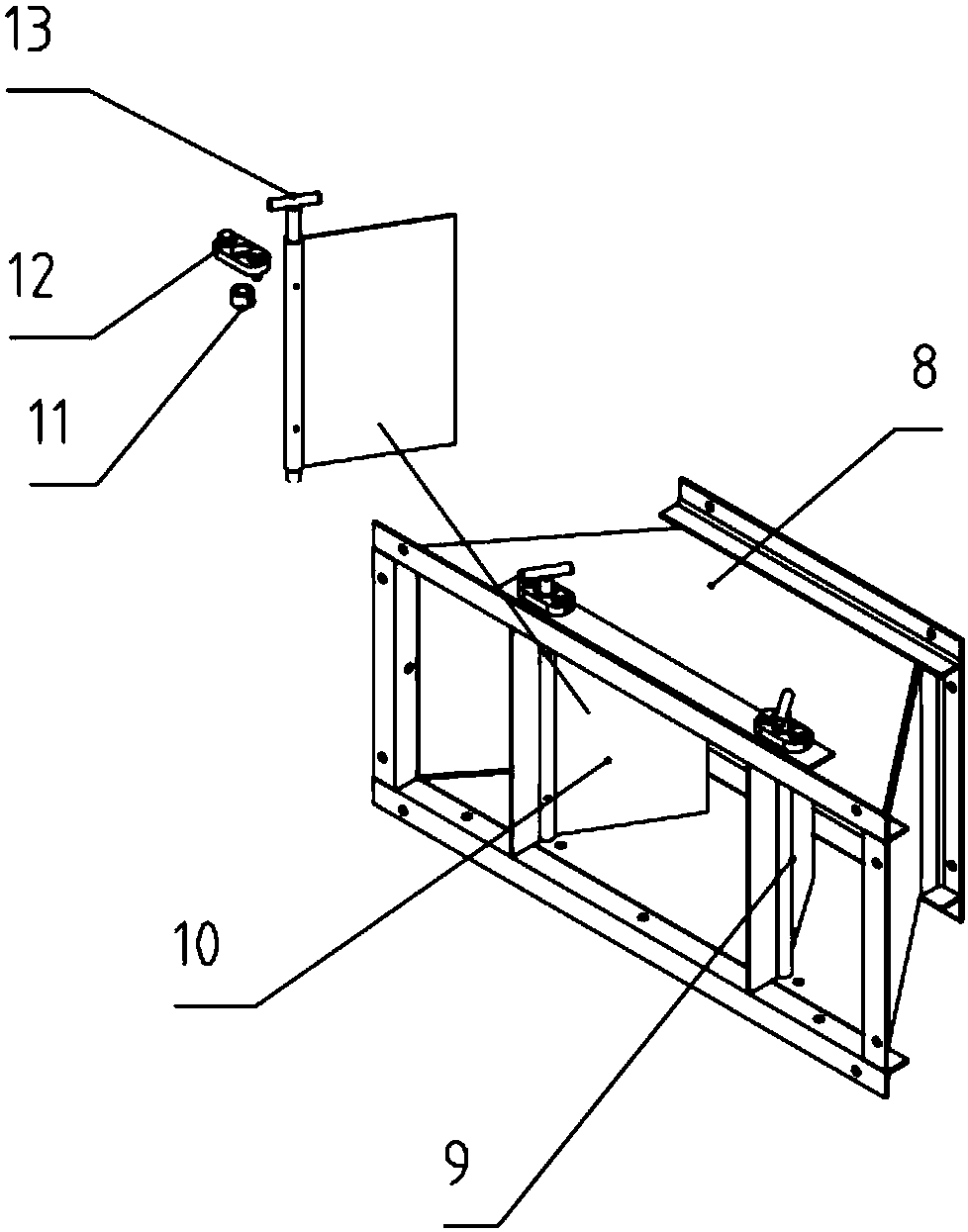
[0030] The specific structure of shunt control device 2 is as follows: figure 2 As shown, it is composed of a variable diameter tube 8 and left and right air deflectors 9 and 10 with adjustable diverging inclination angles, wherein the variable diameter tube 8 is in the shape of a bell mout...
PUM
 Abstract
Description
Claims
Application Information