Plate-strip roller type quenching device and method capable of realizing reverse quenching

A quenching device, plate and strip technology, applied in the direction of quenching device, heat treatment equipment, furnace, etc., can solve problems such as inability to meet, and achieve the effect of improving production efficiency, improving equipment utilization, and expanding the scope of specifications

Inactive Publication Date: 2018-09-04
NORTHEASTERN UNIV
View PDF7 Cites 5 Cited by
  • Summary
  • Abstract
  • Description
  • Claims
  • Application Information

AI Technical Summary

Problems solved by technology

This type of equipment cannot meet the needs of the plate and strip entering the low-pressure cooling section at the rear of the roller quenching machine, and then completing the production processes such as quenching, solid solution, and controlled cooling.

Method used


Image

  • Plate-strip roller type quenching device and method capable of realizing reverse quenching
  • Plate-strip roller type quenching device and method capable of realizing reverse quenching
  • Plate-strip roller type quenching device and method capable of realizing reverse quenching

Examples


Embodiment 1

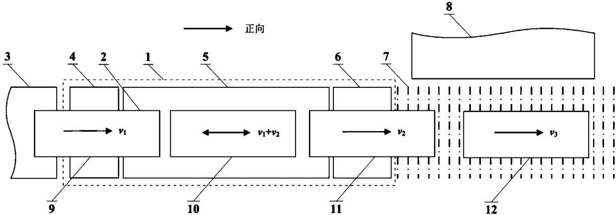
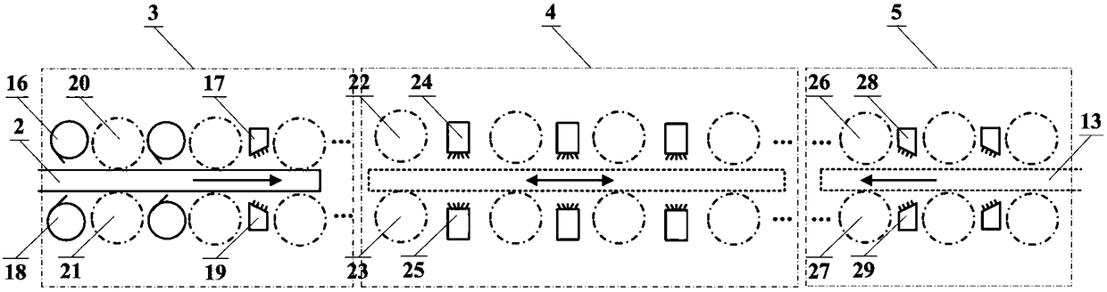
[0023] Embodiment 1, this embodiment provides a forward quenching method implementation process of the present invention, which can realize reverse quenching plate and strip roll quenching device and method, such as figure 1 , 3As shown, choose 6mm thick, 2500mm wide, 8m long plate and strip as an example to illustrate the implementation process. After the forward quenching plate strip 2 is heated to the process temperature in the roller hearth heat treatment furnace 3, the front high-pressure cooling zone 4 and the middle low-pressure cooling zone 5 of the roller quenching device 1 open the upper slit nozzle 16 and the lower slit nozzle in sequence according to the process regulations. Slit nozzles 18, multiple rows of round-hole inclined jet nozzles 17 on the front high-pressure cooling zone, multiple rows of round-hole inclined jet nozzles 19 on the lower front high-pressure cooling zone, upper rows of multi-angle arc-shaped round-hole jet nozzles 24, and lower rows Multi-...

Embodiment 2

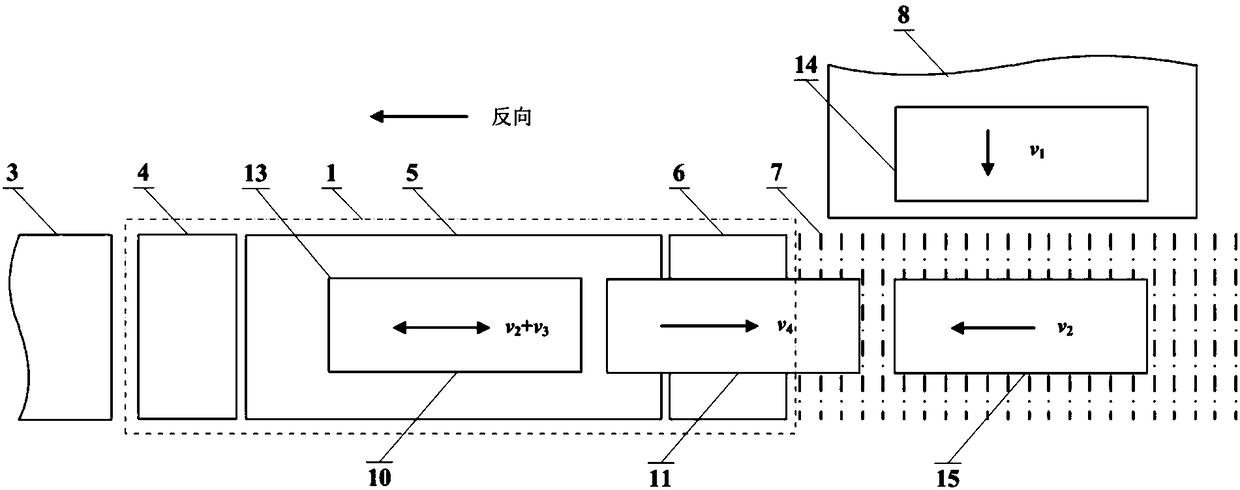
[0024] Embodiment 2. This embodiment provides a reverse quenching method implementation process of a plate and strip roll quenching device and method of the present invention that can realize reverse quenching, such as figure 2 , 3 As shown, choose 80mm thick, 2500mm wide, 8m long plate and strip as an example to illustrate the implementation process. After the reverse quenching plate strip 13 is heated to the process temperature in the external mechanized furnace 8, the rear high-pressure cooling zone 6 and the middle low-pressure cooling zone 5 of the roller quenching device 1 open multiple rows of round holes in the rear high-pressure cooling zone in sequence according to the process regulations Inclined jet nozzles 28, multiple rows of round-hole oblique jet nozzles 29 in the rear high-pressure cooling zone, upper rows of multi-angle arc-shaped round-hole jet nozzles 24, lower rows of multi-angle arc-surface round-hole jet nozzles 25, and upper slit nozzles 16. The lower...


PUM


Abstract

The invention belongs to the technical field of metal plate-strip heat treatment devices, and provides a plate-strip roller type quenching device and a plate-strip roller type quenching method capableof realizing reverse quenching. The device is formed by a front high-pressure cooling area, a rear high-pressure cooling area and a middle low-pressure cooling area; when a plate-strip enters from the front high-pressure cooling area, a forward quenching method is implemented; and when the plate-strip enters from the rear high-pressure cooling area, a reverse quenching method is implemented. According to the device and the method, the utilization rate of the quenching device can be greatly improved; and a special cooling device and a special cooling strategy are adopted for the thin and thickplates-strips, so that the heat treatment plate shapes and the uniformity of the plates-strips are improved at the same time, and multiple purposes are realized through one machine.

Description

technical field [0001] The invention belongs to the technical field of heat treatment equipment for metal plates and strips, and relates to a roll-type quenching device and method for plates and strips that can realize reverse quenching. Background technique [0002] The roller quenching machine has strong cooling capacity, uniform cooling, high production efficiency, good shape of the plate and strip after cooling, equipment length is not limited by the length of the plate and strip, and can realize continuous production. It can be used for carbon steel, stainless steel, special alloy, Titanium alloy, aluminum alloy and other metal plates and strips are produced by quenching, solid solution, and controlled cooling. The thickness range of plate and strip production is 2-300mm, the width range is 1-5m, and the length range is 3-30m. It is the main form of cooling equipment for large-scale heat treatment lines. . For the cooling of plates and strips with a thickness of 2 to 8...

Claims


Application Information

Patent Timeline
Patent Type & Authority Applications(China)
IPC IPC(8): C21D1/667C21D9/46C21D9/00C21D9/52
CPCC21D1/667C21D9/0062C21D9/0081C21D9/46C21D9/52
Inventor 付天亮韩毅王昭东李勇李家栋田勇邓想涛王丙兴
Owner NORTHEASTERN UNIV
Why Eureka
Try Eureka