
Dynamic load sensing device for three-point-suspension space of tractor and working method of dynamic load sensing device

A sensing device, three-point suspension technology, applied in measuring devices, force/torque/work measuring instruments, instruments, etc., can solve problems such as inability to guarantee the actual situation

Active Publication Date: 2018-09-04
NANJING AGRI MECHANIZATION INST MIN OF AGRI
View PDF18 Cites 6 Cited by
  • Summary
  • Abstract
  • Description
  • Claims
  • Application Information

AI Technical Summary

Problems solved by technology

It is only applicable to the height adjustment method (the implement is in a floating state), that is, it is simplified to an ideal two-force rod force state, and the actual situation cannot be guaranteed

Method used


Image

  • Dynamic load sensing device for three-point-suspension space of tractor and working method of dynamic load sensing device
  • Dynamic load sensing device for three-point-suspension space of tractor and working method of dynamic load sensing device
  • Dynamic load sensing device for three-point-suspension space of tractor and working method of dynamic load sensing device

Examples


Embodiment 1

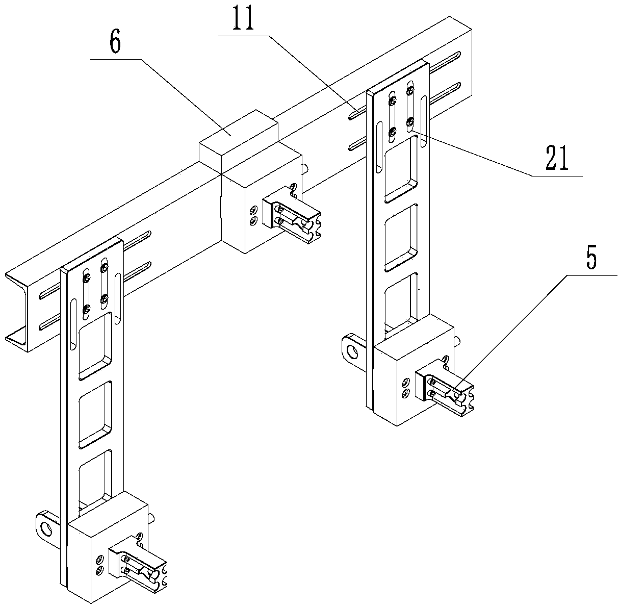
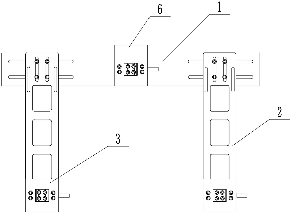
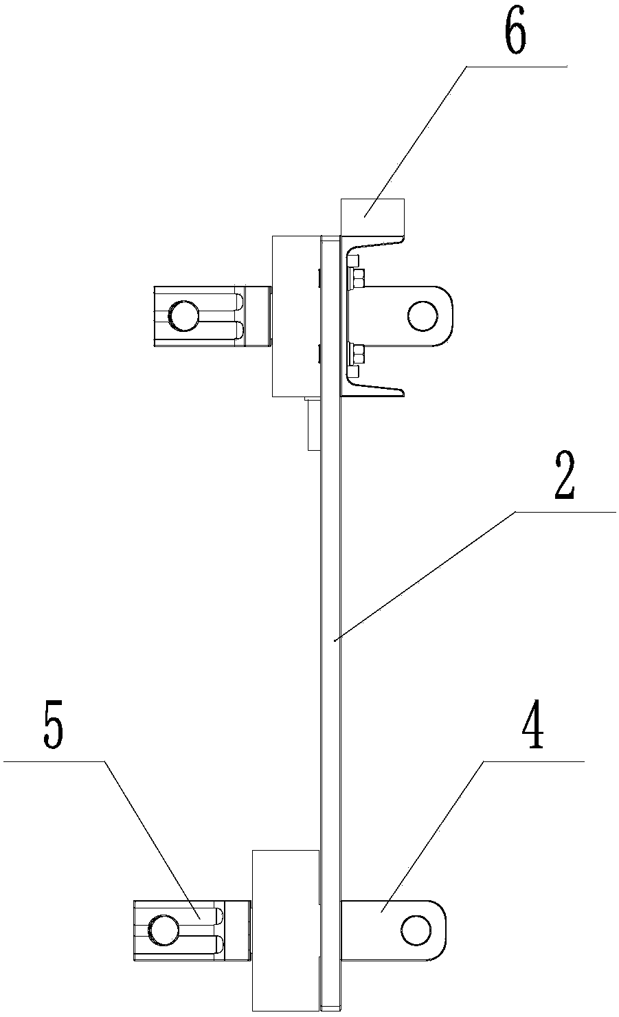
[0041] Embodiment 1: as Figure 1 to Figure 5 The shown base tractor three-point suspension space dynamic load sensing device includes a beam 1, two longitudinal beams 2, three three-component force sensors 3, a first angle sensor 6, a second angle sensor, a beam 1 and two longitudinal beams The beams 2 are connected to form a ∏-shaped frame. The beam 1 and the longitudinal beam 2 are made of steel. The two ends of the beam 1 are provided with a horizontal adjustment groove 11, and the top of the longitudinal beam 2 is provided with a vertical adjustment groove 21. The two longitudinal beams 2 pass through the The bolt at the vertical adjustment groove 21 is fixed with the horizontal adjustment groove 11 of the crossbeam, and the relative position of the longitudinal beam 2 and the crossbeam 1 is adjusted by changing the fixing points of the bolt, the longitudinal adjustment groove 21, and the horizontal adjustment / 11.

[0042]One three-component force sensor 3 is fixed on the...


PUM


Abstract

The invention discloses a dynamic load sensing device for a three-point-suspension space of a tractor and a working method of the dynamic load sensing device. The dynamic load sensing device comprisesa cross beam, two longitudinal beams and three-component force sensors, wherein the cross beam and the two longitudinal beams are connected to form a n-shaped framework, the three-component force sensors are arranged in the middle of the cross beam and the bottoms of the two longitudinal beams, linkage components are respectively arranged on the front and rear sides of the three-component force sensors, the front-side linkage components are used for being connected with the tractor, and the rear-side linkage components are used for being connected with an agricultural implement; the three-component force sensors can be used for measuring the sizes of stresses in the three rectangular coordinate axes X, Y and Z and are arrayed to form a measurement array; and a first angle sensor and a second angle sensor are respectively used for measuring the pitch angles, transverse roll angles and azimuth angles of the sensing device and the tractor and converting measurement results from a coordinate system of the sensing device to a coordinate system of the tractor. According to the sensing device, the component forces of three suspension points in three directions can be simultaneously tested, so that the test of the traction force, lifting force, transverse force and moment of the agricultural implement can be realized.

Description

technical field [0001] The invention relates to the technical field of agricultural machinery, in particular to a three-point suspension space dynamic load sensing device for a tractor. Background technique [0002] The current commonly used methods of traction are the cart-pull method (or towing method), that is, the agricultural implements are suspended by the rear tractor, and the rear unit is pulled by the front tractor. The standard tension sensor is located between the two tractors. The defect is that the test results include Only approximate results can be obtained for the rolling resistance of the rear-mounted tractor itself, and the rolling resistance needs to be tested separately. And only test traction. [0003] In the force measuring pin method, the three suspension pins connecting the tractor and the implement are replaced with force sensors. Most force sensors are one-way load sensors, and the load in a known direction can only be tested according to the insta...

Claims


Application Information

Patent Timeline
Patent Type & Authority Applications(China)
IPC IPC(8): G01L5/16G01L5/00
CPCG01L5/00G01L5/16
Inventor 袁栋姚克恒陈小兵彭卓敏冯健丁艳陈伟夏敏朱继平
Owner NANJING AGRI MECHANIZATION INST MIN OF AGRI
Learn More