Centrifugal impeller static balance automatic debugging machine

An automatic debugging and centrifugal impeller technology, applied in the static/dynamic balance test, machine/structural component test, measuring device, etc., can solve problems such as low efficiency, inconsistent concentricity between the wheel ring and the wheel disc, poor accuracy, etc.

Pending Publication Date: 2018-09-04
王东林
View PDF19 Cites 2 Cited by
  • Summary
  • Abstract
  • Description
  • Claims
  • Application Information

AI Technical Summary

Problems solved by technology

The center of the roulette is connected to the drive shaft, and the concentricity between the outer circumference of the roulette and the center of the roulette can basically meet the requirements. However, the material of the roulette determines that uneven distortion is likely to occur at the outer edge of the roulette (that is, the outer edge of the roulette is in contact with the center of the roulette). The verticality of the central axis of the drive shaft is easily affected)
[0003] The wheel ring is connected to the wheel disk through several blades. Due to the influence of factors such as the connection gap between the wheel ring and the blades and the stiffness of the blades, the concentricity of the wheel r

Method used


Image

  • Centrifugal impeller static balance automatic debugging machine
  • Centrifugal impeller static balance automatic debugging machine
  • Centrifugal impeller static balance automatic debugging machine

Examples


Embodiment Construction

[0029] The present invention will be further described below in conjunction with the accompanying drawings and embodiments.

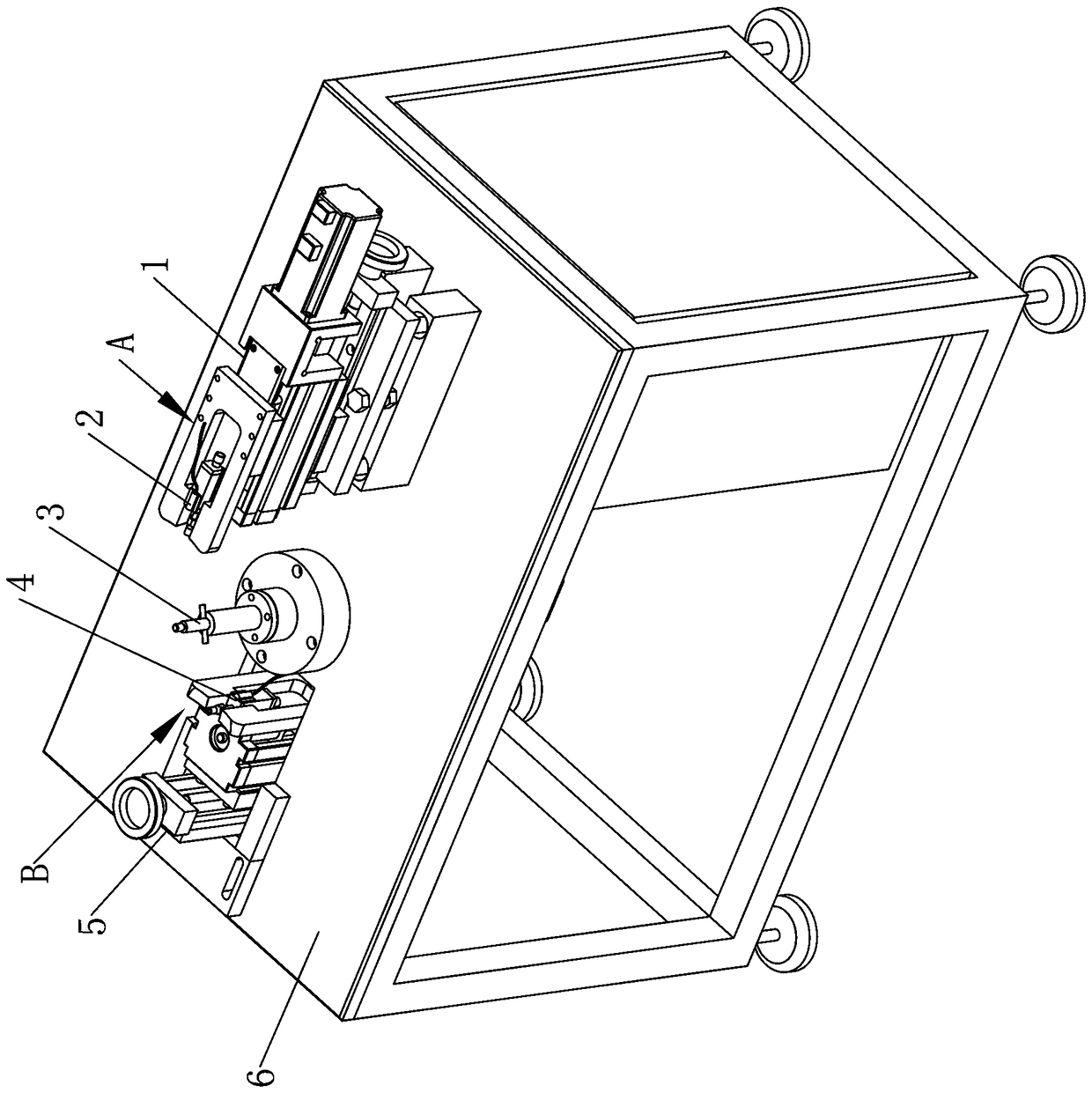
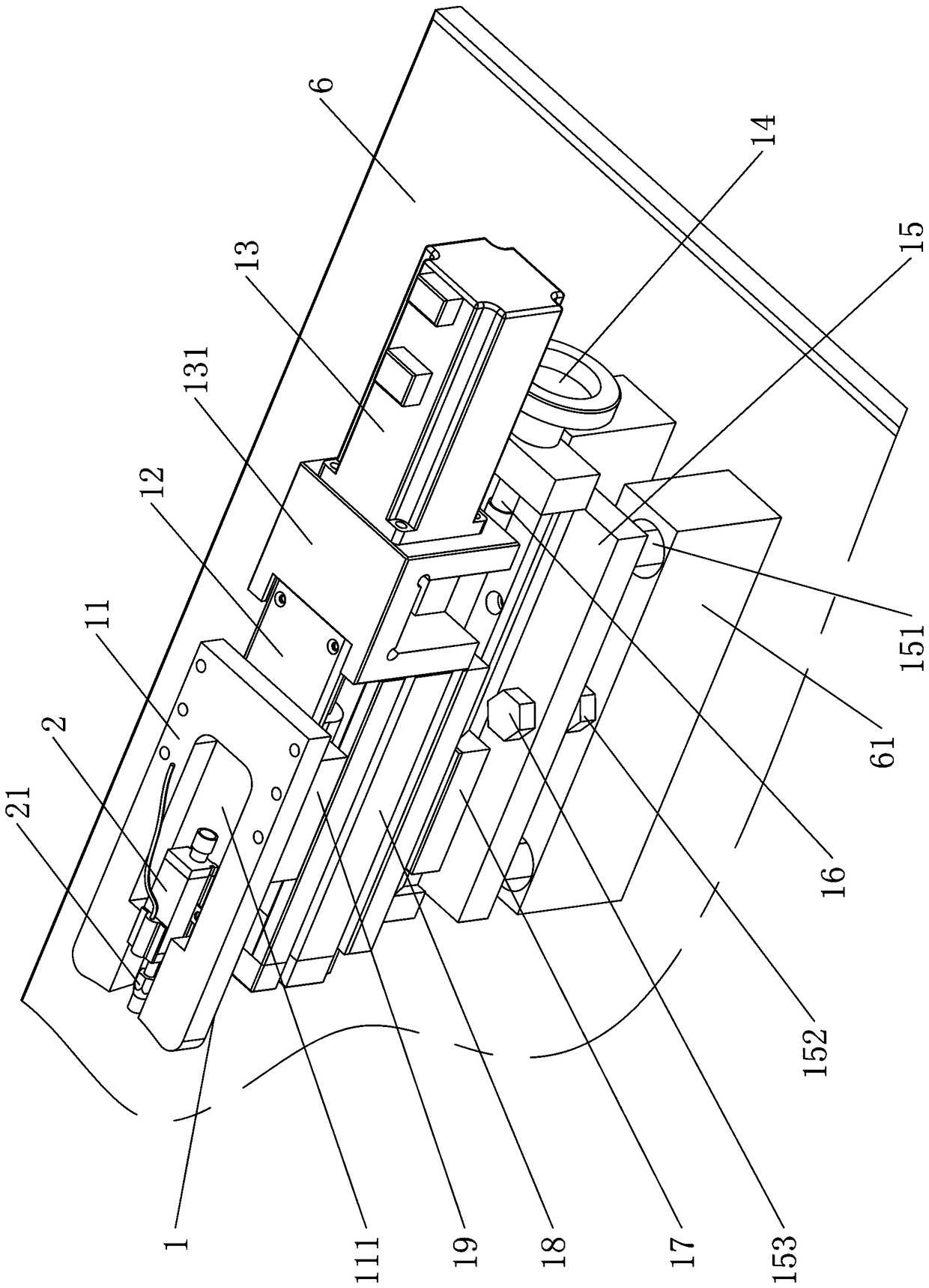
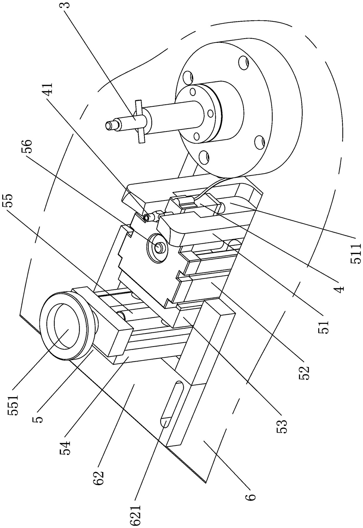
[0030] see Figure 1 to Figure 6 As shown, a centrifugal impeller static balance automatic debugging machine includes a machine platform 6, an impeller shaft 3 is arranged on the machine platform 6, and the impeller shaft 3 is connected to a rotary drive motor 32 in transmission, and a radial data is provided beside the impeller shaft 3. A monitoring assembly 1 and an axial data monitoring assembly 5; the radial data monitoring assembly 1 includes a radial measuring member 2 and a concentricity adjusting member 11 that move radially along the impeller shaft 3, and the axial data monitoring assembly 5 includes The rotating shaft 3 axially adjusts the moving axial measuring member 4 and the verticality adjusting member 51 .

[0031] The radial data monitoring assembly 1 also includes a transverse fixing seat 15, a transverse adjusting seat member, a firs...


PUM


Abstract

The invention relates to a centrifugal impeller static balance automatic debugging machine. The machine comprises a machine bench. The machine bench is provided with an impeller rotating shaft. The impeller rotating shaft is connected to a rotation driving motor in a transmission mode. A radial data monitoring component and/or an axial data monitoring component are arranged beside the impeller rotating shaft. The radial data monitoring component comprises a radial measuring component which is radially adjusted and moved along the impeller rotating shaft and a concentricity adjusting component.The axial data monitoring component comprises an axial measuring component which is axially adjusted and moved along the impeller rotating shaft and a verticality adjusting component. The radial measuring component of the invention can collect the radius data of the centrifugal impeller on the impeller rotating shaft during an impeller rotating shaft rotation process, and the axial measuring component can collect the bottom bounce data of the centrifugal impeller on the impeller rotating shaft during the impeller rotating shaft rotation process. After the above data is collected, the concentricity adjusting component is combined to push the periphery of the centrifugal impeller and the verticality adjusting component is used to push the bottom surface of the centrifugal impeller so that the centrifugal impeller is debugged to a state according with the usage requirement of the centrifugal impeller.

Description

technical field [0001] The invention relates to a centrifugal impeller static balance automatic debugging machine. Background technique [0002] Centrifugal impellers are widely used in range hoods, air conditioners and other electrical appliances. The existing metal centrifugal impellers are mainly composed of discs, blades and rings, and the discs, blades and rings are all stamped from sheet metal. The center of the roulette is connected to the drive shaft, and the concentricity between the outer circumference of the roulette and the center of the roulette can basically meet the requirements. However, the material of the roulette determines that uneven distortion is likely to occur at the outer edge of the roulette (that is, the outer edge of the roulette is in contact with the center of the roulette). The verticality of the central axis of the drive shaft is easily affected). [0003] The wheel ring is connected to the wheel disk through several blades. Due to the influe...

Claims


Application Information

Patent Timeline
IPC IPC(8): G01M1/38
CPCG01M1/12G01M1/36
Inventor 王东林
Owner 王东林
Why Eureka
Try Eureka