Optical module

A technology of optical modules and light beams, which is applied in the field of optical communications and can solve problems such as the weakening of the stability of optical module products

Active Publication Date: 2018-09-04
HISENSE BROADBAND MULTIMEDIA TECH
View PDF5 Cites 4 Cited by
  • Summary
  • Abstract
  • Description
  • Claims
  • Application Information

AI Technical Summary

Problems solved by technology

[0003] However, the above-mentioned monitoring method needs to add an additional spectroscopic device in

Method used


Image

  • Optical module
  • Optical module
  • Optical module

Examples


Embodiment Construction

[0019] In order to further illustrate the principle and structure of the present invention, preferred embodiments of the present invention will now be described in detail with reference to the accompanying drawings.

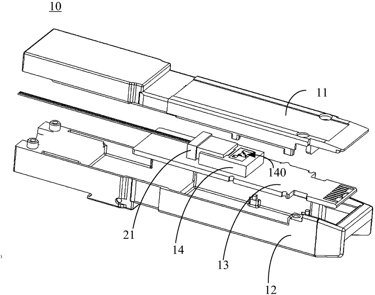
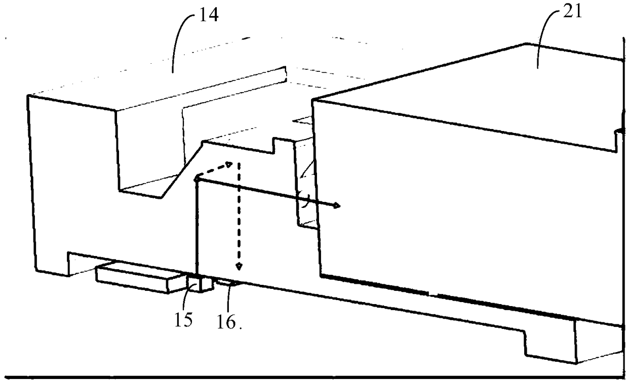
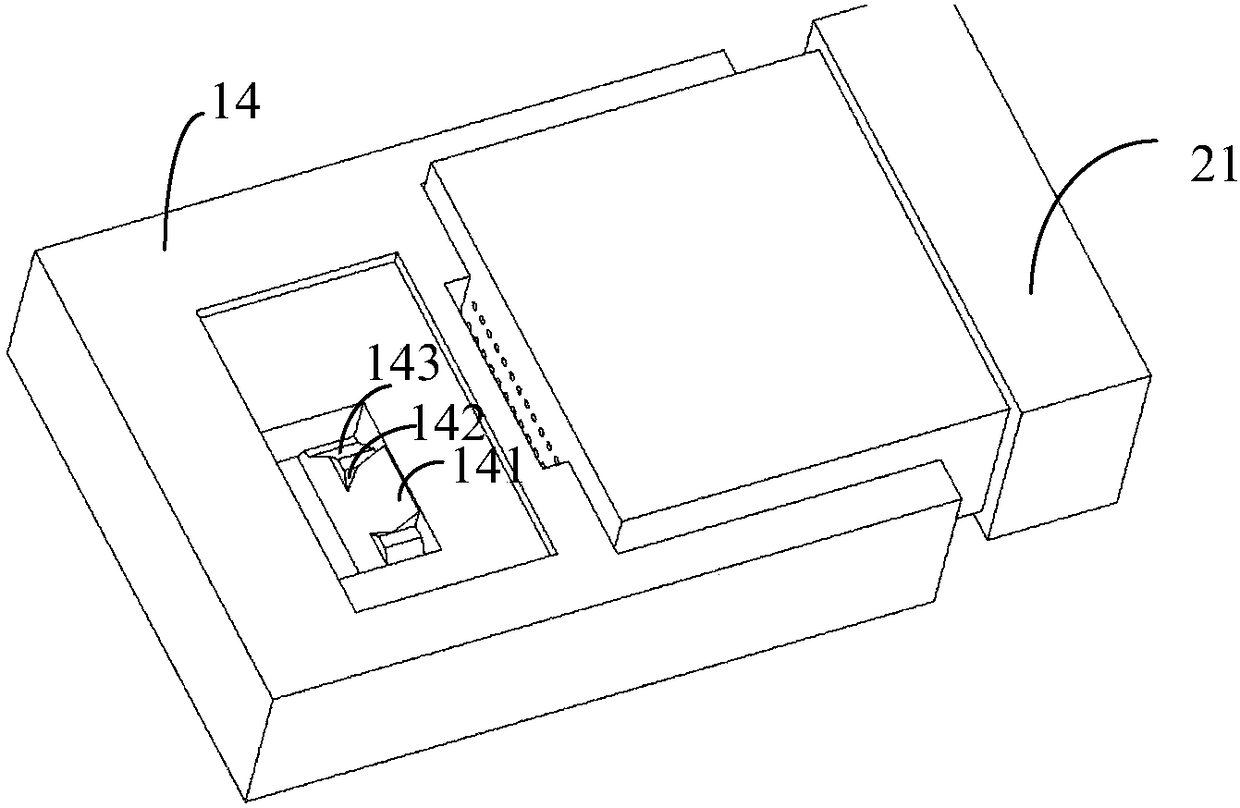
[0020] like figure 1 and figure 2 as shown, figure 1 It is a structural schematic diagram of the optical module of the present invention, figure 2 It is a partial schematic diagram of the optical module. The optical module 10 includes an upper cover 11, a lower cover 12, a circuit board 13, a light emitter 15 integrated on the circuit board 13, a light detector 16, and a lens assembly 14 covering the light emitter 15 and the light detector 16. . The circuit board 13 , the light emitter 15 , the light detector 16 and the lens assembly 14 are all located in the combined space of the upper cover 11 and the lower cover 12 . The external optical fiber adapter 21 is inserted into the casing surrounded by the upper cover 11 and the lower cover 12 , and is clamped...


PUM


Abstract

The invention discloses an optical module. The optical module comprises a circuit board and a lens assembly, wherein an optical transmitter and an optical detector are integrated with the circuit board; the lens assembly is covered above the optical transmitter and the optical detector; a first plane of reflection, a second plane of reflection and a third plane of reflection are formed in the lensassembly; a light beam irradiated on the first plane of reflection is propagated in a first direction after reflection; after a light beam irradiated on second plane of reflection is reflected, the light beam is irradiated on the third plane of reflection in a second direction, is propagated in a third direction after being reflected on the third plane of reflection, and then is incident in the optical detector; and the included angle between the first direction and second direction is 80-100DEG. The optical module reduces the process of manufacturing and increases the stability of product.

Description

technical field [0001] The invention relates to the field of optical communication, in particular to an optical module. Background technique [0002] Optical modules are used for photoelectric signal conversion. Generally, during the operation of the optical module, it is necessary to monitor the laser of the optical module to know the working state of the laser. In the traditional technology, a spectroscopic device, such as a filter, is usually placed on the exit direction of the laser to split the beam emitted by the laser into two paths, one of which is transmitted through the spectroscopic device and coupled to the optical fiber, and the other path passes through the spectroscopic device The reflection is incident to the detector of the optical module, and the detector receives the reflected beam and detects the optical power parameters, thereby realizing the monitoring of the state of the laser. [0003] However, the above-mentioned monitoring method needs to add an a...

Claims


Application Information

Patent Timeline
IPC IPC(8): G02B6/12G02B6/42
CPCG02B6/12G02B6/4201G02B2006/12102G02B2006/12104G02B2006/1215
Inventor 刘旭霞钟岩邵乾
Owner HISENSE BROADBAND MULTIMEDIA TECH
Why Eureka
Try Eureka