A flywheel energy storage array and its energy balance control method

A flywheel energy storage and array technology, applied in the direction of AC network load balancing, can solve the problems of low efficiency and reliability, high system cost, and achieve the effect of improving reliability

Active Publication Date: 2020-09-15
INST OF ELECTRICAL ENG CHINESE ACAD OF SCI
View PDF9 Cites 0 Cited by
  • Summary
  • Abstract
  • Description
  • Claims
  • Application Information

AI Technical Summary

Problems solved by technology

[0006] The purpose of the present invention is to overcome the problems of high cost, low efficiency and reliability of the existing flywheel energy storage technology system, and propose a flywheel energy storage array topology

Method used


Image

  • A flywheel energy storage array and its energy balance control method
  • A flywheel energy storage array and its energy balance control method
  • A flywheel energy storage array and its energy balance control method

Examples


Embodiment 1

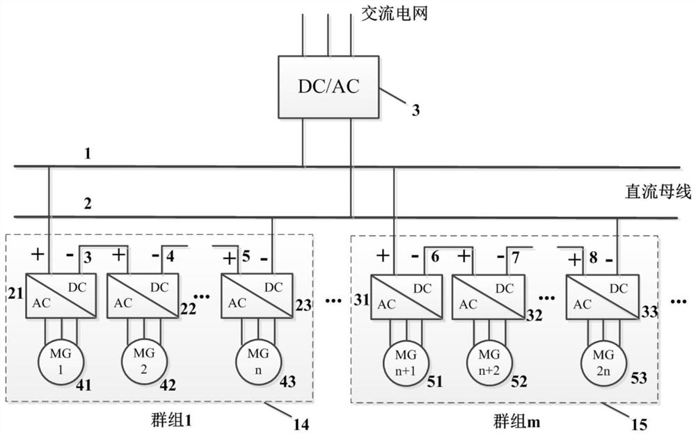
[0036] figure 1 Shown is Example 1 of the present invention. Such as figure 1 As shown, a flywheel energy storage array of the present invention is composed of the first grid-side bidirectional DC / AC converter 3, the first flywheel group 14 and the mth flywheel group 15; the first flywheel group 14 consists of the first Flywheel motor 41, second flywheel motor 42, nth flywheel motor 43, first machine side bidirectional DC / AC converter 21, second machine side bidirectional DC / AC converter 22, nth machine side bidirectional DC / AC converter 23; the mth flywheel group 15 consists of the n+1th flywheel motor 51, the n+2th flywheel motor 52, the 2nth flywheel motor 53, the n+1th machine-side bidirectional DC / AC converter 31, the n+2th It consists of a machine-side bidirectional DC / AC converter 32 and a 2nth machine-side bidirectional DC / AC converter 33 .

[0037] The first lead-out terminal, the second lead-out terminal and the third lead-out terminal of the first grid-side bidir...

Embodiment 2

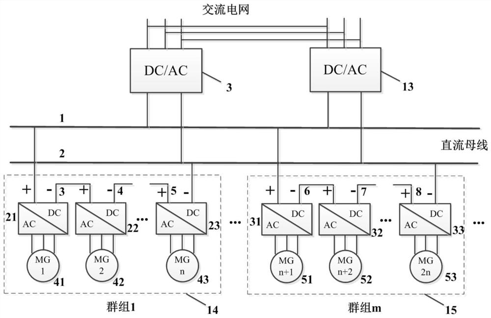
[0044] figure 2 Shown is Example 2 of the present invention. Such as figure 2 As shown, the flywheel energy storage array of the present invention is composed of a first grid-side bidirectional DC / AC converter 3, a second grid-side bidirectional DC / AC converter 13, a first flywheel group 14 and an mth flywheel group 15; The first flywheel group 14 is composed of a first flywheel motor 41, a second flywheel motor 42, an nth flywheel motor 43, a first machine-side bidirectional DC / AC converter 21, a second machine-side bidirectional DC / AC converter 22, a The n machine side bidirectional DC / AC converter 23 is composed; the mth flywheel group 15 is composed of the n+1th flywheel motor 51, the n+2th flywheel motor 52, the 2nth flywheel motor 53, and the n+1th machine side bidirectional DC / AC converter It is composed of an AC converter 31, an n+2th machine-side bidirectional DC / AC converter 32, and a 2nth machine-side bidirectional DC / AC converter 33.

[0045]The first lead-out...

Embodiment 3

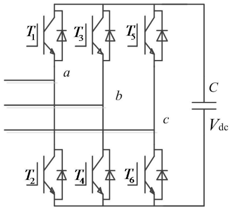
[0048] image 3 , Figure 4 and Figure 5 Shown is Example 3 of the present invention. Such as image 3 , Figure 4 and Figure 5 As shown, in the flywheel energy storage array of the present invention, the first grid side bidirectional DC / AC converter 3, the second grid side bidirectional DC / AC converter 13, the first machine side bidirectional DC / AC converter 21, the second machine side side bidirectional DC / AC converter 22, nth machine side bidirectional DC / AC converter 23, n+1th machine side bidirectional DC / AC converter 31, n+2th machine side bidirectional DC / AC converter 32, and 2n The machine-side bidirectional DC / AC converter 33 can all adopt a two-level structure, a mid-point embedded three-level structure and a modular multi-level structure.


PUM


Abstract

The invention relates to a flywheel energy storage array. The flywheel energy storage array is composed of a first gird-side bidirectional DC / AC converter (3), a first flywheel group (14) and an m-thflywheel group (15); the first flywheel group (14) is composed of a first flywheel motor (41), a second flywheel motor (42), an n-th flywheel motor (43), a first machine-side bidirectional DC / AC converter (21), a second machine-side bidirectional DC / AC converter (22 ) and an n-th machine-side bidirectional DC / AC converter (23); and the m-th flywheel group (15) is composed of a (n+1)-th flywheel motor (51), a (n+2)-th flywheel motor (52), a 2n-th flywheel motor (53), a (n+1)-th machine-side bidirectional DC / AC converter (31), a (n+2)-th machine-side bidirectional DC / AC converter (32), and a 2n-th machine-side bidirectional DC / AC converter (33). According to the flywheel energy storage array of the invention, energy exchange between the flywheel motors and a power grid is achieved by the series-parallel connection of the single flywheel motors and the converters.

Description

technical field [0001] The invention relates to a topology structure of a flywheel energy storage array and an energy balance control method thereof. Background technique [0002] Flywheel energy storage is an energy storage device that stores electrical energy in the form of rotational kinetic energy. Its working principle is to convert excess electrical energy into kinetic energy of the high-speed rotating flywheel rotor and store it; when electrical energy is needed, convert the kinetic energy of the flywheel rotor into electrical energy and release it. Compared with traditional chemical batteries, flywheel batteries have the advantages of high energy density, short charge and discharge time, and long life, so they meet the needs of the world today for environmentally friendly and efficient energy. Flywheel batteries have very broad application prospects in fields such as hybrid electric vehicles and power system peak regulation. [0003] The modern flywheel energy stor...

Claims


Application Information

Patent Timeline
Patent Type & Authority Patents(China)
IPC IPC(8): H02J3/30
CPCH02J3/30Y02E60/16
Inventor 韦统振尹靖元霍群海吴理心
Owner INST OF ELECTRICAL ENG CHINESE ACAD OF SCI
Why Eureka
Try Eureka