Double-joint connection structure between converter transformers and converter valves

A connection structure and converter valve technology, applied in the direction of power transmission AC network, etc., can solve the problems of damage to the terminal post insulator of the converter valve, high seismic intensity, large displacement of the converter valve, etc., to achieve improved seismic performance and offset The effect of earthquake displacement

Pending Publication Date: 2018-09-04
SOUTHWEST ELECTRIC POWER DESIGN INST OF CHINA POWER ENG CONSULTING GROUP CORP
View PDF13 Cites 0 Cited by
  • Summary
  • Abstract
  • Description
  • Claims
  • Application Information

AI Technical Summary

Problems solved by technology

[0003] However, for UHV converter stations located in areas with high seismic intensity, such as areas where the seismic intensity is not lower than 8 degrees, due to the high seismic intensity of the site, the displacement of the converter valve under seismic conditions is relatively large
For example, after actual simulation analysis and calculation, for an 800kV UHV converter station in a high-seismic intensity area, the seismic swing amplitude at the terminal of the high-end 800kV converter valve may reach 1.5m. earthquake resistance
In addition, since the body weight of the 800kV converter valve is 4-5t, if the conventional telescopic tube nut connection scheme is adopted, the seismic stress of the converter valve will cause the The terminal block and post insulator of the flow valve are damaged

Method used


Image

  • Double-joint connection structure between converter transformers and converter valves
  • Double-joint connection structure between converter transformers and converter valves
  • Double-joint connection structure between converter transformers and converter valves

Examples


Embodiment Construction

[0018] In order to make the object, technical solution and advantages of the present invention clearer, the present invention will be described in detail below in conjunction with the accompanying drawings and specific embodiments. It should be understood that the specific embodiments described here are only used to explain the present invention, not to limit the present invention.

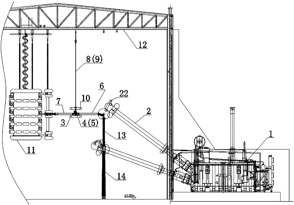
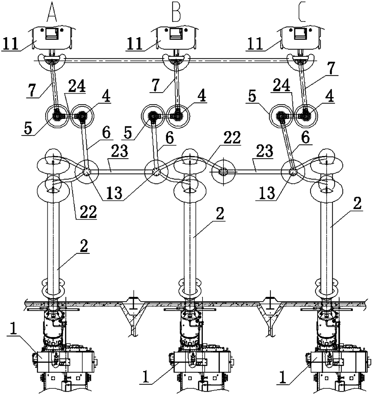
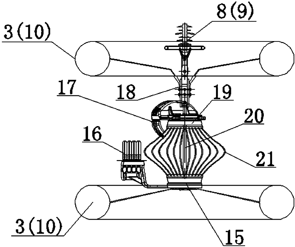
[0019] Such as figure 1 , figure 2 The shown double-joint connection structure between the converter transformer and the converter valve mainly includes the converter transformer 1, the first rotating joint fitting 4, the first suspension insulator 8, the second rotating joint fitting 5 and the second suspension insulator 9 and converter valves 11, wherein each phase converter 1 forms a conductive connection with an independent converter valve 11, and at least one phase converter 1 and the corresponding converter valve 11 are provided with a first rotary joint The hardware 4 , the first suspens...


PUM


Abstract

The invention provides a double-joint connection structure between converter transformers and converter valves. The double-joint connection structure comprises converter transformers and converter valves. Conductive connection is formed between each phase of converter transformer and an independent converter valve. A first rotating joint armour clamp, a first suspension insulator, a second rotating joint armour clamp and a second suspension insulator are arranged between at least one phase of converter transformer and the corresponding converter valve; the two opposite ends of the first suspension insulator are connected with a suspension rack and the first rotating joint armour clamp; and the two opposite ends of the second suspension insulator are connected with the suspension rack and the second rotating joint armour clamp. Conductive connection is formed between the at least one phase of converter transformer and the corresponding first rotating joint armour clamp, second rotatingjoint armour clamp, and converter valve successively. According to the invention, the relatively rotation type movable connection structure is formed between the converter transformers and the converter valves by the first rotating joint armour clamps and the second rotating joint armour clamps, so that the seismic displacement of the converter valve tower is reduced or even cancelled and thus theseismic performance is enhanced.

Description

technical field [0001] The invention relates to the field of connection structure design of a converter transformer and a converter valve, in particular to a double-joint connection structure between a converter transformer and a converter valve. Background technique [0002] The valve side bushing of the converter transformer (referred to as "converter", the same below) is directly inserted into the valve hall, and after the star connection is completed at the end of the post insulator on the valve side through 6 split soft wires in the valve hall, then through The telescopic pipe busbar is connected from the end of the valve-side post insulator to the terminal of the corresponding converter valve. For UHV converter stations in areas with conventional low seismic intensity, due to the small horizontal acceleration of the earthquake, the corresponding swing range of the converter valve under seismic conditions is relatively small. The seismic displacement between the termin...

Claims


Application Information

Patent Timeline
Patent Type & Authority Applications(China)
IPC IPC(8): H02J3/36
CPCH02J3/36Y02E60/60
Inventor 邢毅王强胡蓉任冠雄孙邦新余波许泳吴怡敏周德才李龙才冯千秀胡晓邹家勇李良霄骆玲曾捷樊艳冯川龚琳珺朱忻悦赵宇晖
Owner SOUTHWEST ELECTRIC POWER DESIGN INST OF CHINA POWER ENG CONSULTING GROUP CORP
Why Eureka
Try Eureka