Double-rotation structure between converter transformer and converter valve applied to converter station

A technology for converter valves and converter converters, which is applied to the layout of reels/photosensitive drums, busbars/circuits, etc., and can solve the problem that the wiring arc cannot meet the seismic requirements of converter valves and the bushings on the valve side Terminal damage and other problems can be improved to achieve the effect of improving the seismic performance and offsetting the seismic displacement

Pending Publication Date: 2018-09-14
SOUTHWEST ELECTRIC POWER DESIGN INST OF CHINA POWER ENG CONSULTING GROUP CORP
View PDF0 Cites 4 Cited by
  • Summary
  • Abstract
  • Description
  • Claims
  • Application Information

AI Technical Summary

Problems solved by technology

Obviously, the wiring radian of the soft wire connected by conventional suspension insulators cannot meet the seismic requirements of converter valves in areas with high seismic intensity
In addition, since the body weight of the 800kV converter valve tower is 4-5t, if the conventional suspension insulator is used to connect the flexible wire, the seismic displacement of the converter valve tower will be limited due to the margin of the flexible wire connected to the suspension insulator Therefore, the seismic stress of the converter valve tower will directly pull the valve-side bushing of the converter through the connecting flexible wire, which may cause damage to the terminal of the valve-side bushing of the converter.

Method used


Image

  • Double-rotation structure between converter transformer and converter valve applied to converter station
  • Double-rotation structure between converter transformer and converter valve applied to converter station
  • Double-rotation structure between converter transformer and converter valve applied to converter station

Examples


Embodiment Construction

[0028] In order to make the object, technical solution and advantages of the present invention clearer, the present invention will be described in detail below in conjunction with the accompanying drawings and specific embodiments. It should be understood that the specific embodiments described here are only used to explain the present invention, not to limit the present invention.

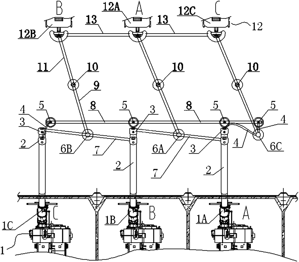
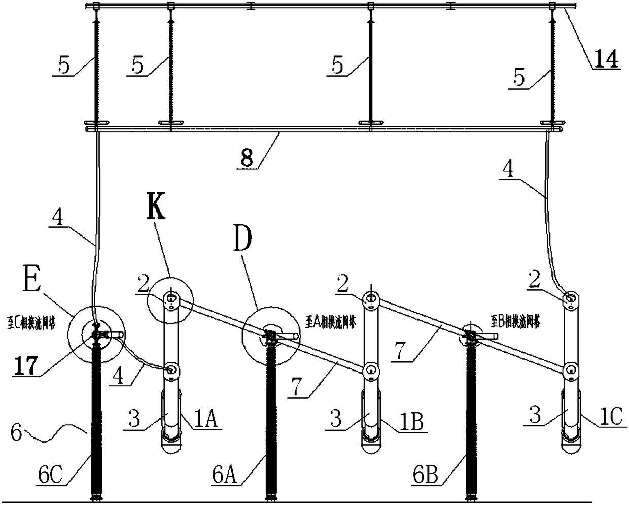
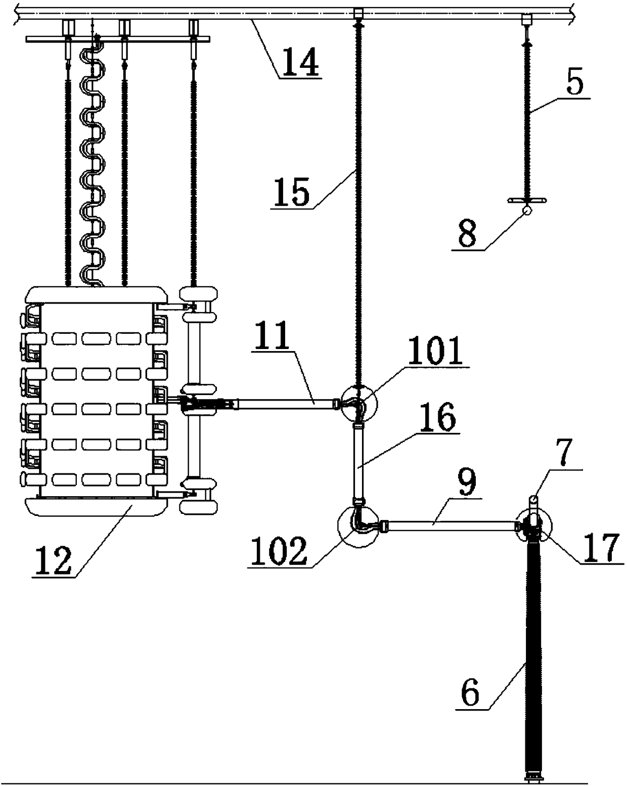
[0029] Such as figure 1 , figure 2 , image 3 The shown connection structure between the angular group converter substation and the converter valve tower of the converter station mainly includes the converter substation 1, the jumper pipe bus 7, the suspension pipe bus 8 and the converter valve tower 12. Transformation 1 includes three phases A, B, and C, which are respectively marked as A-phase commutation rheology 1A, B-phase commutation rheology 1B, and C-phase commutation rheology 1C. Among them, C-phase commutation rheology 1C is defined as side-phase commutation rheology. The diverter v...


PUM


Abstract

The invention provides a double-rotation structure between a converter transformer and a converter valve applied to a converter station. The double-rotation structure comprises converter transformers(1) and converter valves (12); each phase converter transformer (1) is separately connected with each independent converter valve (12) in an electrically conductive manner; rotational joint fittings (10) and second suspension insulators (15) are disposed between at least one phase converter transformer (1) and the corresponding converter valve (12); each rotational joint fitting (10) comprises anupper rotational joint fitting (101) and a lower rotational joint fitting (102); each upper rotational joint fitting (101) is connected with a suspension frame (14) through each second suspension insulator (15); and each upper rotational joint fitting (101) is movably connected with each lower rotating joint fitting (102) in a relative rotation manner. Therefore, under seismic conditions, the seismic oscillations of a converter valve tower in different directions will be converted into a rotational motion of the rotational joint fittings to mitigate or even offset the seismic displacement of the converter valve tower, and the anti-seismic performance of electrical equipment such as the converter valve and the like is further improved.

Description

technical field [0001] The invention relates to the field of connection structure design of a converter transformer and a converter valve, in particular to a double-rotation structure between a converter converter and a converter valve applied to a converter station. Background technique [0002] In the ±800kV UHV converter station, two sets of twelve-pulse converter valves are usually connected in series, and each set of twelve-pulse valves is arranged in a valve hall. The valve-side bushing of the converter transformer (referred to as "converter", the same below) is directly inserted into the valve hall, and is completed between the valve-side bushings of the converter transformer through the suspension pipe busbar or 6-split soft wires in the valve hall. After the corner connection, the pipe bus connected to the end of the suspension insulator is connected to the terminal of the corresponding converter valve tower. For UHV converter stations in conventional low-seismic i...

Claims


Application Information

Patent Timeline
Patent Type & Authority Applications(China)
IPC IPC(8): H02G11/02H02B1/20
CPCH02B1/202H02G11/02
Inventor 邢毅王强胡蓉任冠雄孙邦新余波许泳吴怡敏周德才李龙才冯千秀胡晓邹家勇李良霄骆玲曾捷樊艳冯川龚琳珺朱忻悦赵宇晖
Owner SOUTHWEST ELECTRIC POWER DESIGN INST OF CHINA POWER ENG CONSULTING GROUP CORP
Why Eureka
Try Eureka