Parallel wind power converter system, control method, wind power unit

A technology of wind power converters and electric converters, applied in wind power generation, electrical components, circuit devices, etc., which can solve problems such as interruption of operation due to shutdown switching, affecting efficiency, and the system does not meet the requirements of reactive power support. The effect of optimizing efficiency

Active Publication Date: 2021-07-13
SHENZHEN CHANGHAO MECHANICAL & ELECTRICAL
View PDF0 Cites 0 Cited by
  • Summary
  • Abstract
  • Description
  • Claims
  • Application Information

AI Technical Summary

Problems solved by technology

However, the existing schemes are to cut out or put in the wind power converter in the shutdown state, and for some occasions where the operating conditions change in real time, the shutdown switching will obviously interrupt the operation and affect the efficiency; and for some Where there are reactive power support requirements for high and low voltage ride through, completely removing a certain machine may cause the entire system not to meet the reactive power support requirements for high and low voltage ride through

Method used


Image

  • Parallel wind power converter system, control method, wind power unit
  • Parallel wind power converter system, control method, wind power unit
  • Parallel wind power converter system, control method, wind power unit

Examples


Embodiment 1

[0076] Taking a 5.0MW offshore wind turbine as an example, it is set as a double-winding 2 wind power converter, that is, two wind power converters are connected in parallel, and the control group method is as follows:

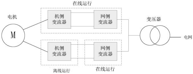
[0077] When the unit starts to run, the grid-side converters of the two wind power converters are turned on first; when the wind speed is low, only the machine-side converter of one wind power converter is turned on, and the other wind power The side converter is in standby mode (such as figure 2 Shown), in order to reduce the converter loss.

[0078] When the wind speed increases and the power generation increases, if it is necessary to increase the number of single units (wind power converters) that are put into operation through the input logic calculation, the machine-side converter of the other wind power converter that was originally in the standby state is put into operation. running, and the torque reference gradually increases from 0 to half of the ...

Embodiment 2

[0081] Take a 6MW wind turbine with 4 windings and 4 converters as an example, that is, 4 wind power converters are connected in parallel, and the power of each wind power converter is 1.5MW (Note: 4 wind power converters are completely consistent), Its operating mode is as follows:

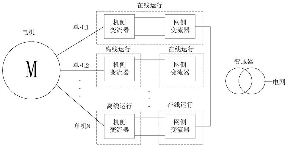
[0082] When the unit is started and running, the grid-side converters of four wind power converters are turned on first; when the wind speed is low, only the machine-side converter of one wind power converter is turned on, and the machine-side converters of the other three wind power converters are turned on. The converter is in a standby state to reduce converter losses.

[0083] When the wind speed increases and the power generation increases, if it is necessary to increase the number of single units (wind power converters) that are put into operation through the input logic calculation, the machine-side converter of one of the wind power converters that was originally in the standby state is p...


PUM


Abstract

The present invention discloses a parallel-connected wind power converter system, a control method, and a wind turbine. The parallel-connected wind power converter system includes N wind power converters connected in parallel, each of which includes a machine-side converter and a wind power converter. For the grid-side converter, the control method includes: the first step, setting the X1 wind power converter to the online mode, and the X2 wind power converter to the semi-offline mode, and X1+X2≦N; the second step, according to Real-time power generation demand, determine the number Y that needs to be added or the number Z that needs to be cut out; the third step is to start Y sets of machine-side converters that are in standby state, so as to realize input; or, control the number Z that needs to be cut out The machine-side converters of the Z wind power converters running online are shut down, and the grid-side converters of the Z wind power converters are kept running online, so as to realize cut-out; this control method enables switching without stopping .

Description

technical field [0001] The invention relates to the technical field of wind power generation, in particular to a parallel wind power converter system, a control method, and a wind turbine. Background technique [0002] With the intensification of the energy crisis, the development and utilization of new energy has become a research focus, especially wind power generation, and the converter is an important part of wind power generation. In recent years, direct-drive power generation converter units have become more and more favored by owners due to their characteristics of no gearbox, high reliability, and low maintenance costs. Drive units have become the absolute mainstream in offshore wind power projects. However, the engineering cost of offshore wind turbines is relatively high. In order to reduce the cost per unit power, large-scale turbines have become the trend of offshore wind power. Therefore, the capacity of supporting motors and full-power converters is also incre...

Claims


Application Information

Patent Timeline
Patent Type & Authority Patents(China)
IPC IPC(8): H02J3/38H02J3/50
CPCH02J3/386H02J3/50Y02E10/76
Inventor 不公告发明人
Owner SHENZHEN CHANGHAO MECHANICAL & ELECTRICAL
Why Eureka
Try Eureka