Oscillator and electronic equipment

A technology of oscillators and resistors, applied in the field of electronic equipment, can solve problems such as increasing the complexity of circuit design and increasing the area of ​​oscillators

Pending Publication Date: 2018-09-04
BOE TECH GRP CO LTD
View PDF4 Cites 0 Cited by
  • Summary
  • Abstract
  • Description
  • Claims
  • Application Information

AI Technical Summary

Problems solved by technology

However, setting the compensation circuit increases the area of ​...

Method used


Image

  • Oscillator and electronic equipment
  • Oscillator and electronic equipment
  • Oscillator and electronic equipment

Examples


Embodiment approach

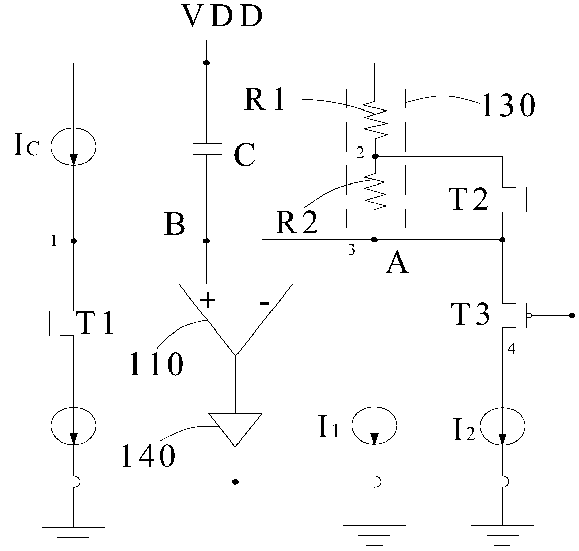
[0082] As an embodiment of the present invention, the first level signal is a high-level signal, and the second level signal is a low-level signal. Accordingly, the first switching transistor T1 and the second switching transistor T2 are N-type transistors, The third switching transistor T3 is a P-type transistor.

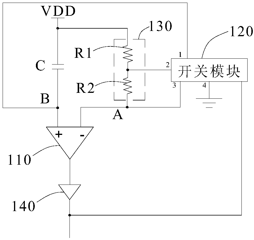
[0083] Below figure 2 The operating principle of the oscillator shown in is described.

[0084] During the charging phase, the voltage of node A rises rapidly, the comparator 110 outputs a high-level first-level signal, the first switching transistor T1 and the second switching transistor T2 are turned on, and the third switching transistor T3 is turned off. At this time, DC signal input terminal VDD input voltage V DD Charge the resistor R1 through the current I1, knowing that the high threshold voltage V is reached OH .

[0085] In the discharging phase, when the voltage of node B exceeds the voltage of node A, the output state of the comparator 110 changes, and a ...


PUM


Abstract

The invention provides an oscillator. The oscillator comprises a comparator, a capacitor, a DC signal input end, and a reference voltage input end; the oscillator further comprises a switch module anda resistor module; the resistor module comprises a first resistor and a second resistor; the first end of the first resistor is electrically connected with the DC signal input end, the second end ofthe first resistor is electrically connected with the first end of the second resistor, the second end of the second resistor is electrically connected with the reference voltage input end, and the temperature coefficient of the first resistor is in contrast to the temperature coefficient of the second resistor; the first pole of the capacitor is electrically connected with the DC signal input end, and the second pole of the capacitor is electrically connected with the positive input end of the comparator. The invention further provides electronic equipment; the oscillator is simple in structure and small in temperature shift coefficient.

Description

Technical field [0001] The present invention relates to the field of electronic equipment, and in particular to an oscillator and an electronic equipment including the oscillator. Background technique [0002] Oscillators are an indispensable part of electronic devices such as televisions and mobile phones, so as to provide clock signals for electronic devices. The current oscillators include RC oscillators and LC oscillators. [0003] Oscillators are more sensitive to temperature. In view of this, current oscillators are mostly equipped with compensation circuits to reduce the output frequency with temperature changes. However, the provision of a compensation circuit increases the area of ​​the oscillator and also increases the complexity of circuit design. [0004] Therefore, how to simplify the circuit design of the oscillator has become an urgent technical problem in this field. Summary of the invention [0005] The object of the present invention is to provide an oscillator an...

Claims


Application Information

Patent Timeline
IPC IPC(8): H03B5/04
CPCH03B5/04
Inventor 杨全高延凯
Owner BOE TECH GRP CO LTD
Why Eureka
Try Eureka