
Method and system for designing large two-layer network architecture based on containers

A large layer 2 network and container technology, applied in the field of virtual communication exchange, can solve problems such as unfavorable maintenance, inability to use automated tools to manage, and scalability easily limited by physical devices, so as to improve deployment efficiency and facilitate management and maintenance. Effect

Inactive Publication Date: 2018-09-04
云家园网络技术有限公司
View PDF5 Cites 8 Cited by
  • Summary
  • Abstract
  • Description
  • Claims
  • Application Information

AI Technical Summary

Problems solved by technology

[0002] The use of Internet architecture has a long history. With the rapid expansion of the network scale and the continuous enrichment of business types, the structure and functions of the Internet are becoming increasingly complex. The main disadvantage is that it requires a large number of physical devices and the difficulty of network management and control is increasing. It is difficult to quickly deploy new network functions, and the scalability is easily limited by physical equipment. It cannot be managed by automated tools, which is not conducive to later maintenance.
When combined with virtualization technologies such as docker (application container engine), traditional networks cannot meet the increasingly flexible and changeable requirements of enterprise-level networks, and cannot make full use of the performance of physical devices, nor can they make full use of the benefits provided by virtualization technologies. Advantages of resource isolation brought about by namespace isolation

Method used


Image

  • Method and system for designing large two-layer network architecture based on containers
  • Method and system for designing large two-layer network architecture based on containers
  • Method and system for designing large two-layer network architecture based on containers

Examples


Embodiment 1

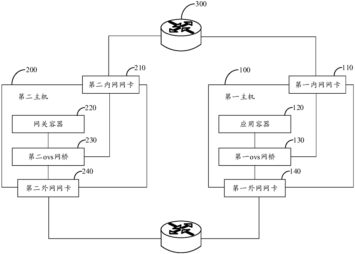
[0046] figure 1 It is a network topology model diagram provided by Embodiment 1 of the present invention.

[0047] The open source software openvswitch is used as the infrastructure for network communication between containers, and its software simulation network (SDN) function is used to build a large layer-2 network based on containers, such as figure 1As shown, the design system of a large layer-2 network based on containers includes multiple hosts, such as the first host 100 and the second host 200 shown in the figure; each host includes a container, an ovs bridge, and two physical network cards. The containers are divided into an application container 120 and a gateway container 220, which are respectively set on the first host 100 and the second host 200. The ovs bridge on each host is respectively connected to the container and different physical network cards; and two physical network cards on different hosts are used to establish the physical connection of the networ...

Embodiment 2

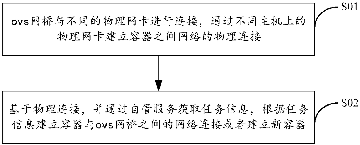
[0049] figure 2 It is a flowchart of a design method of a container-based large layer-2 network provided by Embodiment 2 of the present invention.

[0050] Based on the container-based large layer 2 network design system provided in the above embodiments, the network topology construction method includes two aspects: establishing network connections and performing network management, such as figure 2 Shown:

[0051] In step S01, the ovs network bridge is connected to different physical network cards, and a physical network connection between containers is established through physical network cards on different hosts.

[0052] Step S02, based on the physical connection, obtain task information through the self-management service, and establish a network connection between the container and the ovs bridge or establish a new container according to the task information.

[0053] For step S01, refer to figure 1 , the ovs bridge is connected to the external network card and the...


PUM


Abstract

The invention provides a method and a system for designing a large two-layer network architecture based on containers, and relates to the technical field of virtual communication switching. The methodcomprises the steps of: connecting OVS (Open vSwitch) network bridges with different physical network cards, establishing a physical connection of a network between containers through the physical network cards on different host computers; acquiring task information through self-managed service based on the physical connection, and establishing a network connection between the containers and theOVS network bridges or establishing a new container according to the task information. Through adoption of the above technical scheme, the method of the invention can improve deployment efficiency ofa network, and is beneficial to management and maintenance of equipment.

Description

technical field [0001] The invention relates to the technical field of virtual communication switching, in particular to a design method and system of a container-based large two-layer network architecture. Background technique [0002] The use of the Internet architecture has a long history. With the rapid expansion of the network scale and the continuous enrichment of business types, the structure and functions of the Internet are becoming increasingly complex. The main disadvantage is that a large number of physical devices are required, and the difficulty of network management and control is increasing day by day. It is difficult to quickly deploy new network functions, and the scalability is easily limited by physical equipment. It cannot be managed by automated tools, which is not conducive to later maintenance. When combined with virtualization technologies such as docker (application container engine), traditional networks cannot meet the increasingly flexible and ch...

Claims


Application Information

Patent Timeline
IPC IPC(8): H04L12/24H04L12/46
CPCH04L12/462H04L41/0803H04L41/12H04L41/5041
Inventor 孟宪宇李军禹睿博梁伟
Owner 云家园网络技术有限公司
Learn More