Automatic keyboard illuminating circuit used for automated teller machine

An automatic teller machine and automatic lighting technology, applied in lighting devices, electric light sources, electrical components, etc., can solve the problems of shortening the life of high-brightness LED lights, increasing the cost of electricity consumption, etc. Effect

Pending Publication Date: 2018-09-04
昆明理工大学津桥学院
View PDF0 Cites 0 Cited by
  • Summary
  • Abstract
  • Description
  • Claims
  • Application Information

AI Technical Summary

Problems solved by technology

[0002] At present, ATMs are required to install a keyboard lighting system according to the needs of banks. Most of the designs choose to directly light up the high-brightness LED lights from the perspective of cost, regardless of time, so that the design c

Method used


Image

  • Automatic keyboard illuminating circuit used for automated teller machine

Examples


Example Embodiment

[0014] The technical solutions in the embodiments of the present invention will be clearly and completely described below in conjunction with the accompanying drawings in the embodiments of the present invention. Obviously, the described embodiments are only a part of the embodiments of the present invention, rather than all the embodiments. Based on the embodiments of the present invention, all other embodiments obtained by those of ordinary skill in the art without creative work shall fall within the protection scope of the present invention.

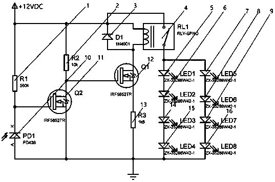
[0015] Such as figure 1 As shown, the automatic lighting circuit of the keyboard for the automatic teller machine includes resistor R1 (1), resistor R2 (2), diode D1 (3), relay RL1 (4), highlight light emitting diode LED1 (5), highlight light Diode LED2 (6), highlight light emitting diode LED5 (7), highlight light emitting diode LED6 tube (8), highlight light emitting diode LED7 (9), photodiode PD1 (10), N-channel MOSFET tube Q2 (11) , ...


PUM


Abstract

The invention relates to an automatic keyboard illuminating circuit used for automated teller machine, comprising a resistor R1 (1), a resistor R2 (2), a diode D1 (3), a relay RL1 (4), a highlight light emitting diode LED1 (5), a highlight light emitting diode LED2 (6), a highlight light emitting diode LED5 (7), a highlight light emitting diode LED6 (8), a highlight light emitting diode LED7 (9),a photosensitive diode PD1 (10), an N channel MOSFET tube Q2 (11), an N channel MOSFET tube Q1 (12), a resistor R3 (13), a highlight light emitting diode LED3 (14), a highlight light emitting diode LED4 (15), and a highlight light emitting diode LED8 (16). The resistance value of the photosensitive diode PD1 (10) arranged on an automated teller machine keyboard cover is increased along with reduction of illumination intensity, resulting in cutoff of the N channel MOSFET tube Q2 (11), and then causing rising and breakover of voltage of a control grid of the N channel MOSFET tube Q1 (12), and therefore, the relay RL1 (4) is electrified primarily, and then the highlight light emitting diodes are conducted to give out light to light up the keyboard.

Description

technical field [0001] The invention relates to an automatic lighting circuit for a keyboard used in an automatic teller machine. Background technique [0002] At present, ATMs are required to install a keyboard lighting system according to the needs of banks. Most of the designs choose to directly light up the high-brightness LED lights from the perspective of cost, regardless of time, so that the design circuit is simple and the cost is low, but it will increase The cost of electricity will significantly shorten the life of high-brightness LED lights. Generally speaking, the high-brightness LED lights on the light board need to be replaced every six months. Contents of the invention [0003] In order to solve the above problems, the present invention provides an automatic lighting circuit for a keyboard of an automatic teller machine. The circuit can automatically adjust the lighting light according to the ambient light intensity of the ATM, so as to save electricity co...

Claims


Application Information

Patent Timeline
IPC IPC(8): H05B33/08H05B44/00
CPCH05B45/10
Inventor 熊浩
Owner 昆明理工大学津桥学院
Why Eureka
Try Eureka