Control method, modular joint robot and storage medium

A control method and robot technology, applied in the direction of program control manipulators, manipulators, manufacturing tools, etc., can solve the problems of difficult programming learning and high learning threshold, and achieve the effect of low learning threshold, lower development threshold and low design cost.

Inactive Publication Date: 2018-09-07
SHENZHEN YUEJIANG TECH CO LTD
View PDF8 Cites 4 Cited by
  • Summary
  • Abstract
  • Description
  • Claims
  • Application Information

AI Technical Summary

Problems solved by technology

[0004] The purpose of the present invention is to provide a control method, a modular articulated robot and a storage medium, aiming at solving the problems in the prior art such as the high learning threshold for robot design and the difficulty in programming and learning

Method used


Image

  • Control method, modular joint robot and storage medium
  • Control method, modular joint robot and storage medium
  • Control method, modular joint robot and storage medium

Examples


Embodiment 1

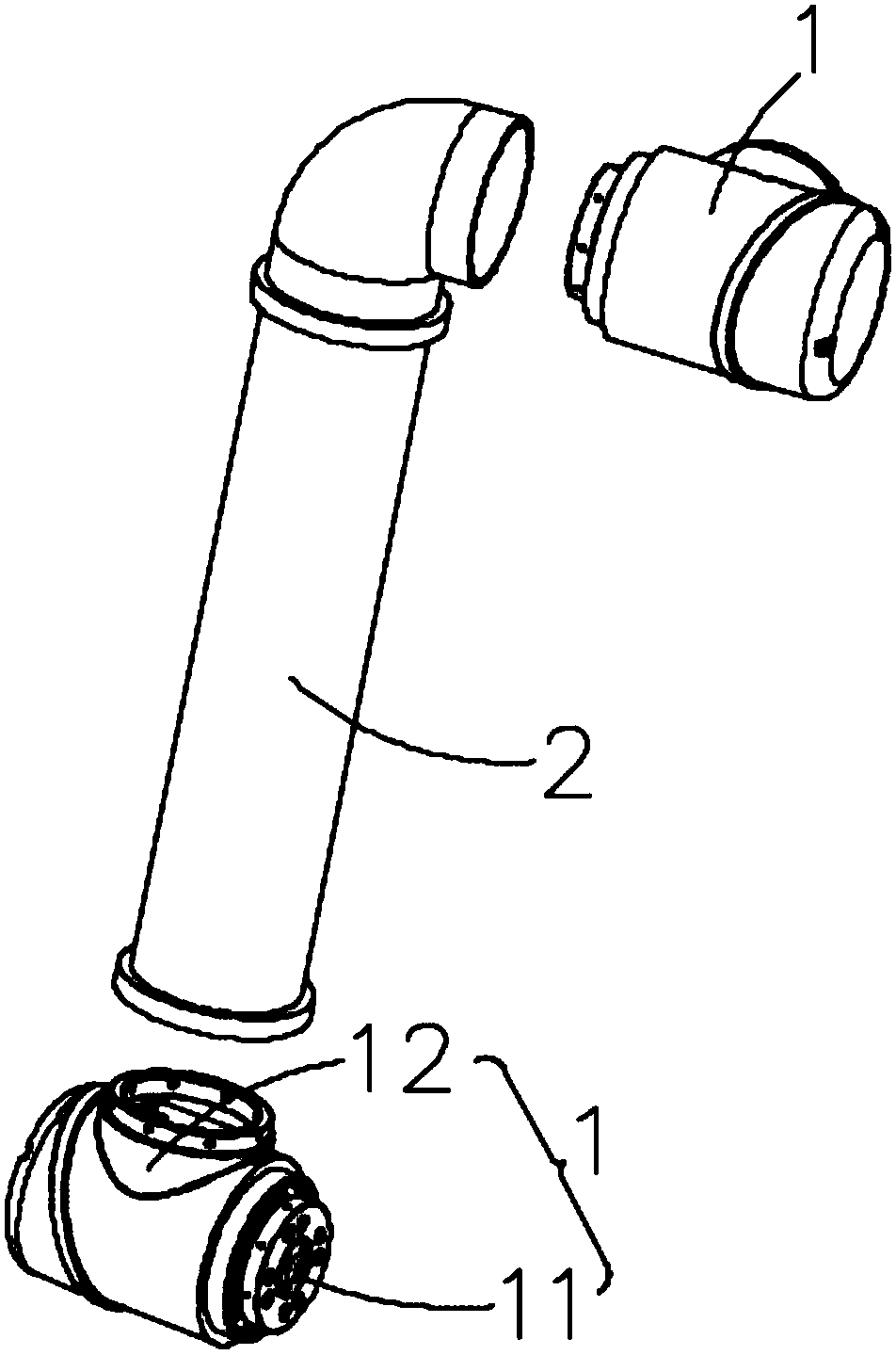
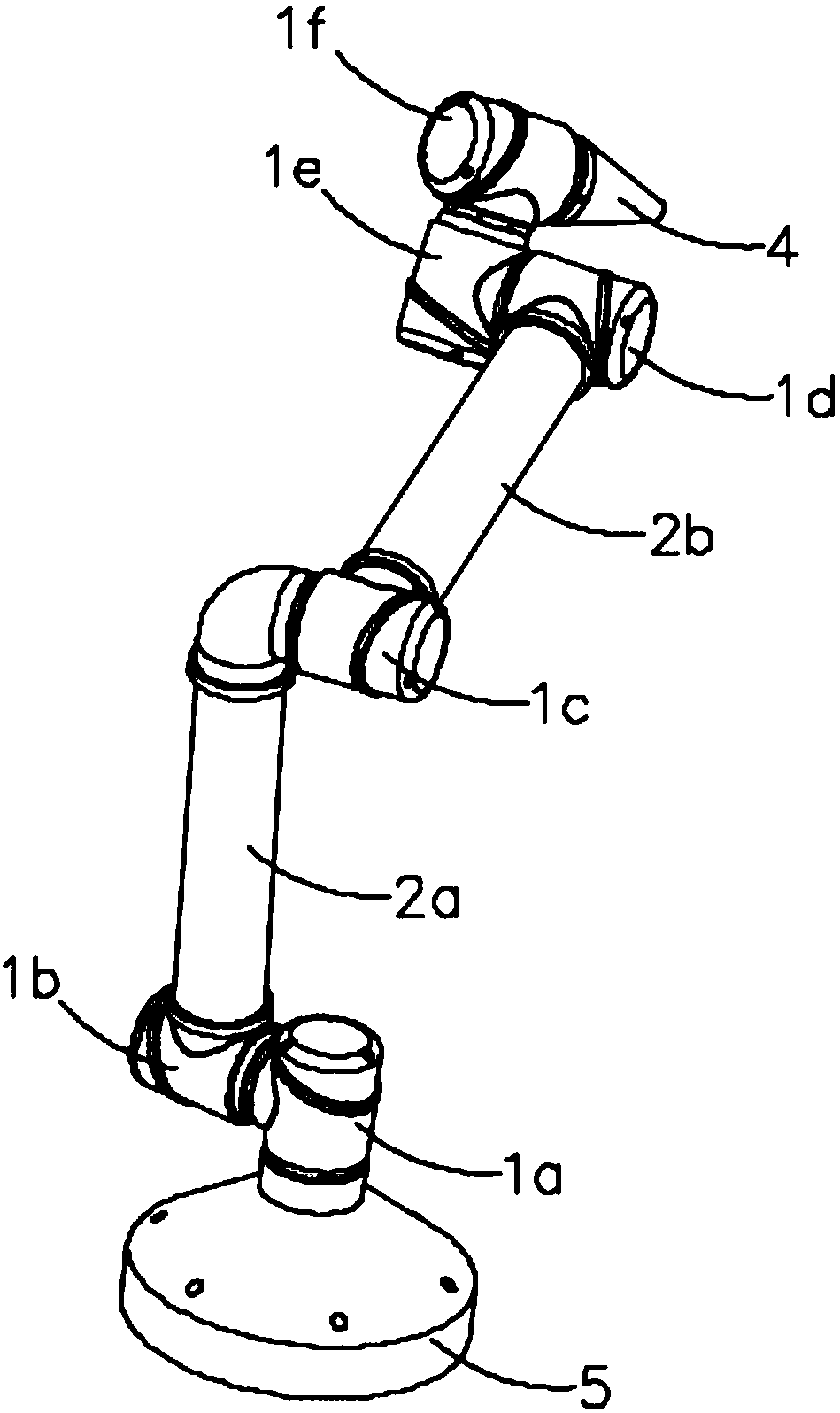
[0025] Such as Figure 1 to Figure 4 As shown, a modular articulated robot is provided in this embodiment, including a plurality of articulated arms 2, a plurality of articulated modules 1, and a control system 3; wherein, the articulated module 1 is installed at the end of the articulated arm 2 for driving two Adjacent articulated arms 2 relatively swing.

[0026] The joint module 1 includes a fixing base 12 , a motor installed in the fixing base 12 and an output shaft 11 . The joint module 1 can be installed in various ways, for example, the fixed base 12 is installed at the end of one articulated arm 2, and the output shaft 11 is connected to the end of another articulated arm 2; or the fixed base 12 is installed at the end of an articulated arm 2 , the output shaft 11 is connected to the fixing seat 12 of another joint module 1 . Driven by the motor, the output shaft 11 rotates to output torque. The fixed seat 12 is equivalent to the stator. After the output torque, the ...

Embodiment 2

[0037] Such as Figure 1 to Figure 4 As shown, a control method is provided in this embodiment for controlling a joint robot, including:

[0038] Provide preset function modules and logic configuration trees, each function module is used to drive a single motor, and the logic configuration tree has multiple nodes for placing function modules and parameter setting options corresponding to each node;

[0039] Accept the user's setting data for the logical configuration tree and convert it into robot control instructions;

[0040] Transmit control commands to the articulated robot.

[0041] Since the programming of the robot requires a certain learning threshold, the control method provided in this implementation uses a modular programming idea to directly provide functional modules that have been debugged and compiled. Functional modules are placed into nodes of the logical configuration tree. The logical configuration tree itself has a logical sequence. By adjusting the corr...


PUM


Abstract

The invention relates to the technical field of robots and discloses a modular joint robot, a control method and a storage medium. The modular joint robot comprises a plurality of joint arms, a plurality of joint modules and a control system; each joint module comprises a fixing seat, a motor mounted in the fixing seat and an output shaft, wherein the output shaft is connected to the tail end of the corresponding joint arm or the fixing seat of another joint module; the control system comprises a control panel and a driving plate which is used for directly driving all the joint modules; the control panel comprises a processing chip which is used for operating a software platform; and the driving plate is electrically connected with the control panel. The modular joint robot and the controlmethod can directly integrate high-difficulty controlled portions, the robot development threshold is lowered, the robot can enter the ordinary life from the field of professional application, and then the blue ocean market of the robots is opened up.

Description

technical field [0001] The invention relates to the technical field of robots, in particular to the technical field of drive-control integrated and modular robots. Background technique [0002] The robot mainly includes the following parts: structural part and control part. Among them, the structural part includes the motor and the related big arm, forearm, base, executive structure, etc. The motor is generally installed at the joint, and after its rotation, it drives the corresponding structure to swing or rotate, such as forearm swing, big arm swing, finger opening, etc. Together and so on. , the control part includes the controller, the driver and the teaching pendant. The controller is responsible for the trajectory planning and control part of the upper layer, and outputs the control signal. , and finally make the bot run. During operation, the motor feeds back motion information to the driver, and the driver learns the degree of motion based on the feedback informat...

Claims


Application Information

Patent Timeline
Patent Type & Authority Applications(China)
IPC IPC(8): B25J9/06B25J9/08B25J9/16
CPCB25J9/06B25J9/08B25J9/161
Inventor 刘培超郎需林刘主福庄飞飞
Owner SHENZHEN YUEJIANG TECH CO LTD
Why Eureka
Try Eureka