Elevator weighing device detection equipment and method

A weighing device and detection equipment technology, applied in the field of elevators, can solve problems such as the inability to continuously adjust the load quality, time-consuming and labor-intensive handling of weights, equipment handling, troublesome operation, etc., to achieve simple and fast adjustment and light weight , On-site operation is convenient

Active Publication Date: 2018-09-07
SHANGHAI MITSUBISHI ELEVATOR CO LTD
View PDF4 Cites 1 Cited by
  • Summary
  • Abstract
  • Description
  • Claims
  • Application Information

AI Technical Summary

Problems solved by technology

If it is prepared on site (for example, making cement blocks on site), it is difficult to ensure accurate weight, and the reuse rate is also very low;
[0007] 2. During on-site operation, every time the load is adjusted, it needs to be carried by manpower, and the labor cost is high
It is very time-consuming and labor-intensive to carry heavy weights, and the efficiency is very low;
[0008] 3. Since each weight block has a fixed mass, the load mass cannot be continuously adjusted during the test;
[0009] 4. All the weights are placed in the car, and it is easy to cause damage to the surface of the car during the handling process
[0013] 1. It needs to be realized by very complex special equipment. Although it can be reused, such special equipment itself has high cost. Due to its large size and heavy weight, it is troublesome to carry and operate the equipment;
[0014] 2. The loading position is on the bottom of the car or on the top of the car, and it needs to be operated at the landing, while the control equipment of the elevator and the controller of the weighing device are generally located in the machine room
This makes operation cumbersome and difficult for one-person operation

Method used


Image

  • Elevator weighing device detection equipment and method
  • Elevator weighing device detection equipment and method
  • Elevator weighing device detection equipment and method

Examples


Embodiment Construction

[0049] The realization, functional characteristics and beneficial effects of the present invention will be further described below in conjunction with specific embodiments and accompanying drawings.

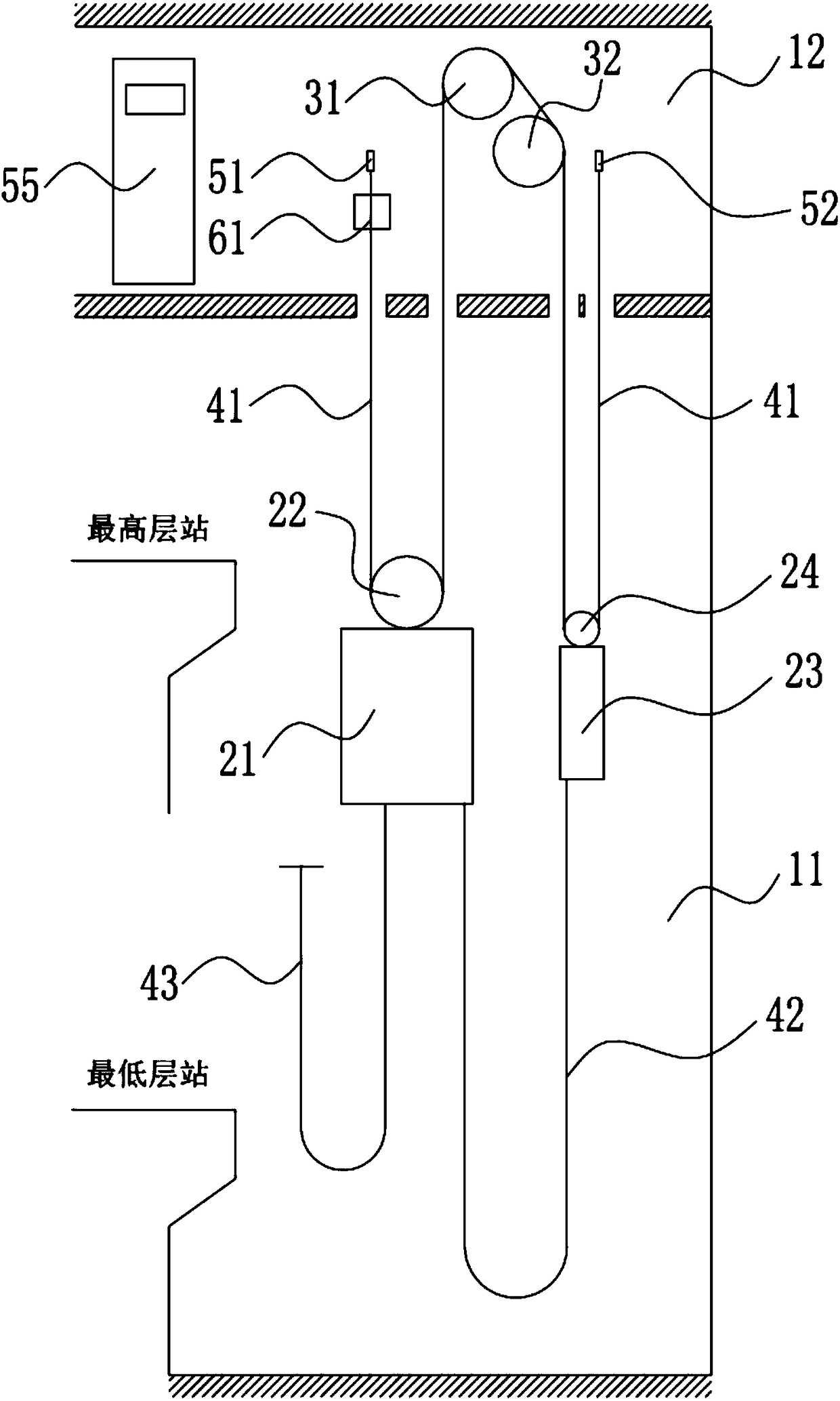
[0050] like figure 1Shown is a schematic diagram of the elevator system. In the elevator system, the car 21 and the counterweight 23 are arranged in the hoistway 11, guided by the car guide rail and the counterweight guide rail respectively, suspended by the traction rope 41 wound on the driving device 31, and passed through the machine room 12. The driving force of the driving device 31 in the lifting channel 11 moves in the opposite direction to each other along the vertical direction. This figure shows the machine-room elevator with the most common roping ratio i=2 at present. The car 21 is provided with a car side pulley 22, and the counterweight 23 is provided with a counterweight side pulley 24. The traction rope 41 walks around the car side pulley 22 and the counterweigh...


PUM


Abstract

The invention discloses elevator weighing device detection equipment. The elevator weighing device detection equipment comprises a lever mechanism, a force applying device and a lever mechanism connecting device, wherein the lever mechanism is used for loading at the elevator rope head position, the force applying device is used for applying force to the lever mechanism, and the lever mechanism connecting device is used for fixing connecting the lever mechanism to the elevator rope head position. According to the detection equipment, when a weighing device is debugged or detected, weight blocks do not need to be moved into a lift car any more, and all loading operation can be completed in a machine room. The elevator weighing device detection equipment has the beneficial effects of being simple in structure, low in cost, small in weight, small in size, convenient to transport and the like; universality is high, the equipment can be applied to different elevator construction sites and most elevator types, and the reusing rate is high; and spot operation is convenient to operate, one-person operation is easy, loading is simple and quick, load continuous adjustment can be convenientlyand quickly achieved. The invention further discloses an elevator weighing device detection method.

Description

technical field [0001] The invention belongs to the field of elevators, and in particular relates to a detection device for an elevator weighing device. The invention also relates to a detection method for an elevator weighing device. Background technique [0002] The weighing device is an important part of the elevator system. It has the function of overload protection for the elevator and is extremely important for ensuring the personal safety of passengers, the goods being transported, and the safety of the elevator itself. In addition, the weighing device accurately feeds back the actual load in the car, which helps the elevator control equipment to accurately determine the starting torque of the traction machine, etc., and is conducive to improving the ride comfort of the elevator. [0003] Not only in the initial stage of elevator installation and commissioning, it is necessary to write scales to the weighing device, but according to the requirements of TSG T5001-2009...

Claims


Application Information

Patent Timeline
Patent Type & Authority Applications(China)
IPC IPC(8): B66B5/00G01G23/01
Inventor 李丰甘靖戈
Owner SHANGHAI MITSUBISHI ELEVATOR CO LTD
Why Eureka
Try Eureka