
Mechanical lifting equipment

A lifting equipment and mechanical technology, applied in the direction of lifting frame, lifting device, etc., can solve problems such as accidents, complex structure of hydraulic lifting device, loss of bearing capacity of hydraulic lifting device, etc., to reduce production costs, reduce structural complexity and ease of use The effect of the failure rate

Inactive Publication Date: 2018-09-07
LINYI UNIVERSITY
View PDF6 Cites 2 Cited by
  • Summary
  • Abstract
  • Description
  • Claims
  • Application Information

AI Technical Summary

Problems solved by technology

However, the structure of the hydraulic lifting device is relatively complex and delicate. Once the hydraulic oil in the hydraulic system loses pressure, the hydraulic lifting device will lose its carrying capacity and cause an accident. At the same time, the working conditions of the hydraulic device are relatively high. Once the equipment fails, Its maintenance and repair costs are relatively high

Method used


Image

  • Mechanical lifting equipment
  • Mechanical lifting equipment
  • Mechanical lifting equipment

Examples


Embodiment Construction

[0023] Embodiments of the present invention will be further described below in conjunction with the accompanying drawings.

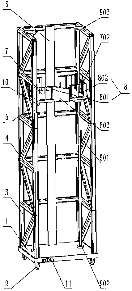
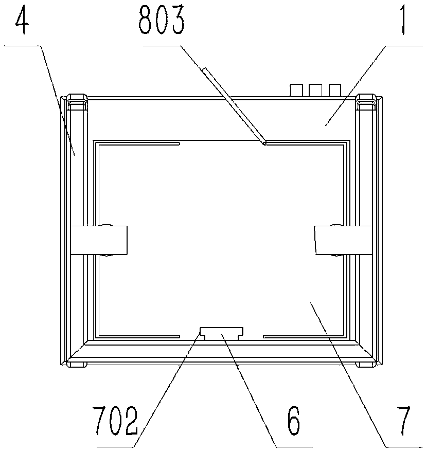
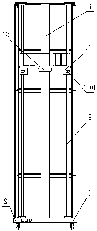
[0024] Please see attached figure 1 to attach image 3 Shown, a kind of mechanical lifting equipment comprises base 1, caster 2, support bar 3, beam 4, diagonal brace 5, guide rail plate 6, lifting platform 7, guardrail 8, lead screw mechanism 9 and rotating motor 10; The base 1 is a rectangular metal plate, and the four casters 2 are respectively arranged on the four corners of the bottom surface of the base 1; the support rod 3 is a square tube, and the four support rods 3 are respectively It is arranged on the four corners of the top surface of the base 1 by welding; the beam 4 is a square tube; several beams 4 are arranged on both sides of the base 1 along the axial direction of the support rod 3 Above the short side and a long side, and the beam 4 is connected with the support bar 3 by welding; the diagonal brace 5 is a square tube, and the diagon...


PUM


Abstract

The invention discloses mechanical lifting equipment. The mechanical lifting equipment comprises a base, casters, support rods, cross beams, inclined struts, a guide rail plate, a lifting platform, aguardrail, a lead screw mechanism and a rotating motor. The mechanical lifting equipment has the beneficial effects that the lead screw mechanism is adopted to replace a hydraulic lifting mechanism and a rack-and-pinion mechanism, so that the structural complexity and the use failure rate of the lifting equipment can be remarkably reduced while the lifting function of the lifting equipment can besatisfied, and the production cost and maintenance cost of the lifting equipment can be effectively reduced.

Description

technical field [0001] The invention relates to the technical field of machinery, in particular to a mechanical lifting device. Background technique [0002] Working at heights requires the use of lifting equipment to bring people and equipment between the work site and the ground. At present, existing lifting equipment mainly adopts the mode of hydraulic lifting. However, the structure of the hydraulic lifting device is relatively complicated and fine. Once the hydraulic oil in the hydraulic system loses pressure, the hydraulic lifting device will lose its carrying capacity and cause an accident. At the same time, the working conditions of the hydraulic device are relatively high. Once the equipment fails, Its maintenance and repair costs are also relatively high. Contents of the invention [0003] The object of the present invention is to provide a mechanical lifting device to solve the deficiencies in the prior art. [0004] In order to achieve the above object, the ...

Claims


Application Information

Patent Timeline
IPC IPC(8): B66F7/14B66F7/28
CPCB66F7/14B66F7/28
Inventor 王春梅
Owner LINYI UNIVERSITY
Learn More