Device for separating moisture in sludge

A technology for sludge and moisture, applied in the field of devices for separating moisture in sludge, can solve the problems of unreasonable structural settings, immature technical solutions, poor separation effect, etc., and achieves the effects of rapid water loss, convenient later replacement, and convenient treatment.

Inactive Publication Date: 2018-09-07
朱梓瑜
View PDF4 Cites 16 Cited by
  • Summary
  • Abstract
  • Description
  • Claims
  • Application Information

AI Technical Summary

Problems solved by technology

[0002] In the process of urban river construction, a large amount of silt needs to be processed and transported away for other purposes, but because silt generally contains more water and has strong fluidity, transportation is inconvenient
How to achieve faster and better effective separation of sludge and water is a technical problem that needs to be solved. In order to solve this technical problem, various methods and settings for separating sludge and water have emerged as the times require, but the existing devices Or setting, or due to unreasonable structure setting, or immature technical solution, there are deficiencies and defects of poor separation effect
Therefore, there is still a large room for improvement in the existing technology

Method used


Image

  • Device for separating moisture in sludge
  • Device for separating moisture in sludge
  • Device for separating moisture in sludge

Examples


Embodiment Construction

[0018] The following will clearly and completely describe the technical solutions in the embodiments of the present invention with reference to the accompanying drawings in the embodiments of the present invention. Obviously, the described embodiments are only some, not all, embodiments of the present invention.

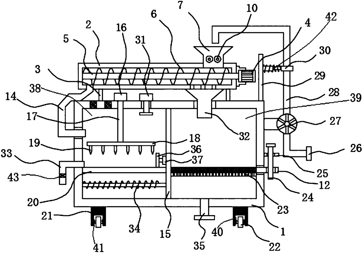
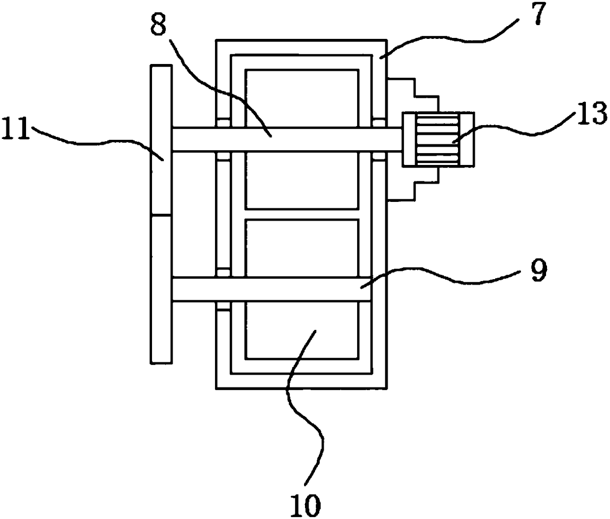
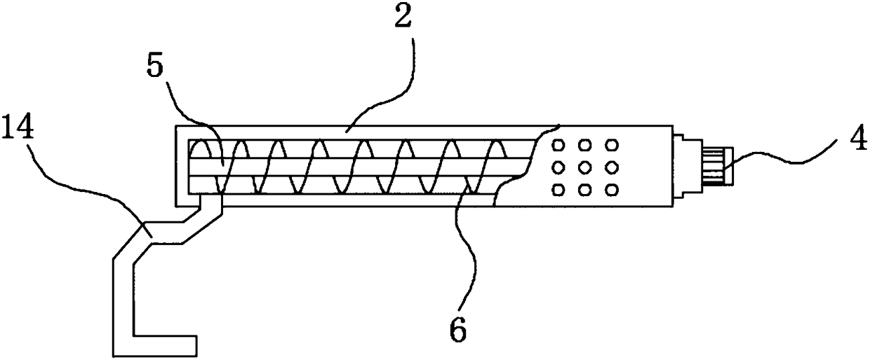
[0019] refer to Figure 1-3 , a device for separating moisture in sludge, comprising a treatment box 1, the top of the treatment box 1 is fixedly connected with an exhaust fan 31, the input end of the exhaust fan 31 runs through the top of the treatment box 1 and extends to the inside of the sludge chamber 38, and the top of the sludge chamber 38 There are cooling holes corresponding to the exhaust fan 31, and the exhaust fan 31 can accelerate the air circulation in the sludge chamber 38, so that the water in the sludge can be lost faster. The top of the treatment box 1 is provided with a feeding cylinder 2, and A plurality of connecting rods 3 are fixedly connected ...


PUM


Abstract

The invention discloses a device for separating moisture in sludge. The device comprises a treatment box; a feeding cylinder is arranged above the treatment box and is fixedly connected with the treatment box through a plurality of connecting rods; a rotating rod is rotationally connected with the inside of the feeding cylinder; a first rotating motor is fixedly connected with one side of the feeding cylinder, and the output end of the first rotating motor penetrates through the side wall of the feeding cylinder and is fixedly connected with the rotating rod; a helical blade is fixedly sheathed on the rotating rod, and the outer side of the helical blade is matched with the inner side wall of the feeding cylinder; a feed hopper is arranged at the top of the feeding cylinder; a feeding mechanism corresponding to the feed hopper is arranged on one side of the treatment box; a first rotating shaft and a second rotating shaft are respectively and rotationally connected with the inside of the feed hopper; a crushing wheel is fixedly sheathed on each of the first rotating shaft and a second rotating shaft. The device disclosed by the invention is compact in structure, convenient and quick to operate, capable of realizing the sludge and moisture separation and realizing separate treatment and good in separation effect.

Description

technical field [0001] The invention relates to the technical field of sludge treatment, in particular to a device for separating moisture in sludge. Background technique [0002] During the construction of urban rivers, a large amount of silt needs to be processed and transported away for other purposes. However, silt generally contains more water and has strong fluidity, which makes transportation inconvenient. How to achieve faster and better effective separation of sludge and water is a technical problem that needs to be solved. In order to solve this technical problem, various methods and settings for separating sludge and water have emerged as the times require, but the existing devices Or setting, or due to unreasonable structural setting, or immature technical scheme, there are deficiencies and defects of poor separation effect. Therefore, there is still much room for improvement in the prior art. Contents of the invention [0003] The purpose of the present inve...

Claims


Application Information

Patent Timeline
Patent Type & Authority Applications(China)
IPC IPC(8): C02F11/00C02F11/12C02F11/121C02F11/125C02F11/13
CPCC02F11/00C02F11/121C02F2103/007C02F2303/26C02F11/125C02F11/13C05F7/00B01D29/03Y02A40/20C05F17/50
Inventor 朱梓瑜
Owner 朱梓瑜
Why Eureka
Try Eureka