High-strength precise ball hinge applied to die-cutting machine

A high-strength, die-cutting machine technology, applied in mechanical equipment, metal processing, shafts and bearings, etc., can solve the problems of high punching force, high punching frequency of die-cutting machine, and die-cutting machine can no longer work normally, and achieves a high level of improvement. The effect of service life and strength improvement

Pending Publication Date: 2018-09-07
无锡市正先自动化设备有限公司
View PDF1 Cites 2 Cited by
  • Summary
  • Abstract
  • Description
  • Claims
  • Application Information

AI Technical Summary

Problems solved by technology

[0004] Due to the high punching frequency and high punching force of the die-cutting machine, the ball hinge as the main force-bearing component often suffers damage to the ball joint shaft. Once the ball joint shaft breaks, the die-cutting machine can no longer work normally.

Method used


Image

  • High-strength precise ball hinge applied to die-cutting machine
  • High-strength precise ball hinge applied to die-cutting machine
  • High-strength precise ball hinge applied to die-cutting machine

Examples


Embodiment Construction

[0030] Specific embodiments of the present invention will be described in detail below in conjunction with the accompanying drawings.

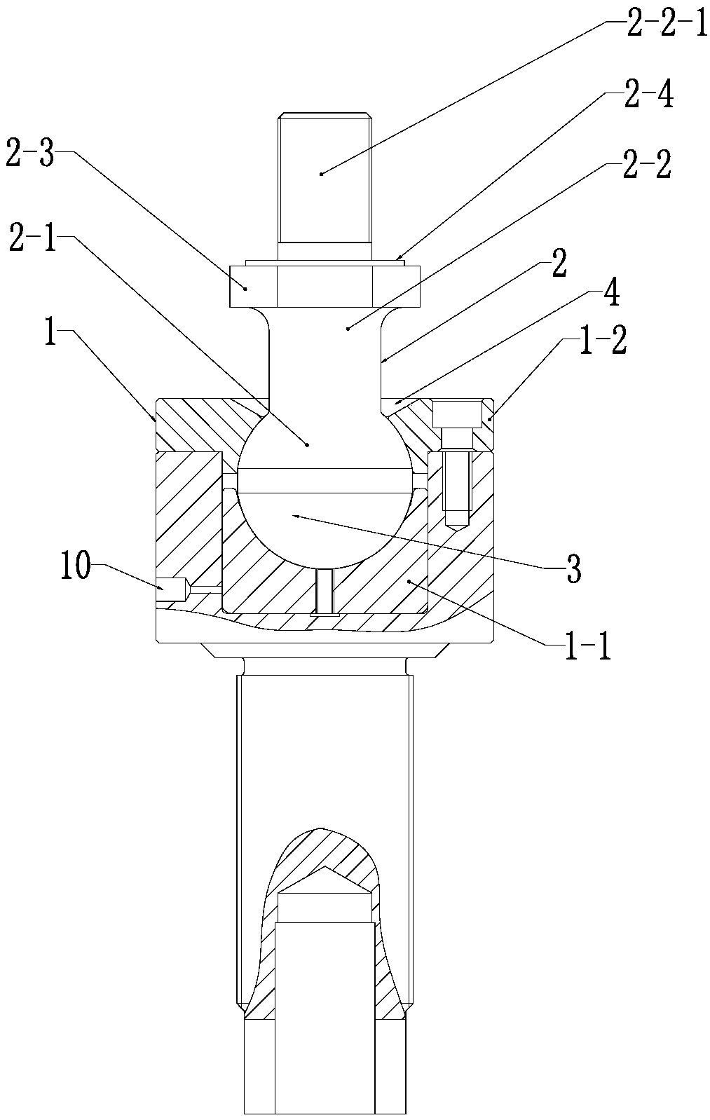
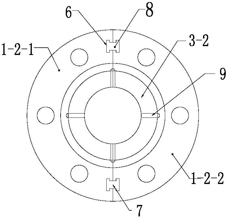
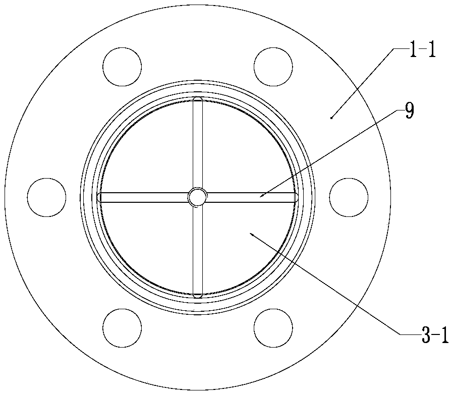
[0031] Such as Figure 1 ~ Figure 4 The high-strength ball hinge applied to the die-cutting machine shown includes a ball socket 1 and a ball head shaft 2. The ball socket 1 is provided with a ball cavity 3, and the ball socket 1 is provided with a tapered hole 4 communicating with the ball cavity 3. , the ball shaft 2 includes a ball head 2-1 that is articulated with the ball cavity 3 and a screw shaft 2-2 that is connected to the ball head 2-1 at one end and has a threaded section 2-2-1 at the other end. The screw shaft 2-2 at the root of the section 2-2-1 extends radially outward to form a thrust ring 2-3 with a diameter larger than the diameter of the screw shaft 2-2, and the end of the thrust ring 2-3 facing the screw shaft 2-2 is A thrust platform 2-4 perpendicular to the axial direction of the screw shaft 2-2.

[0032] By adding a thr...


PUM

PropertyMeasurementUnit
Thicknessaaaaaaaaaa

Abstract

The invention relates to a high-strength precise ball hinge applied to a die-cutting machine; the ball hinge includes a ball socket and a ball head shaft; the ball socket is internally provided with aball cavity and is provided with a taper hole communicating with the ball cavity; the ball head shaft includes a ball head and a threaded rod shaft, wherein the ball head is in hinge joint cooperation with the ball cavity, one end of the threaded rod shaft is connected on the ball head, and the other end of the threaded rod shaft is provided with a threaded section; a part, at the root part of athreaded section, of the threaded rod shaft radially extends outwards to form a thrust ring having the diameter greater than that of the threaded rod shaft; one end, facing the threaded rod shaft, ofthe thrust ring is a thrust platform perpendicular to the axial direction of the threaded rod shaft; by increasing of the thrust ring, a larger contact face of the thrust ring is used for supporting the high-frequency stamping force of the die-cutting machine, so the pressure on the root part of the threaded section can be reduced, the strength of the whole ball hinge can be improved, and the service life of the ball hinge is prolonged.

Description

Technical field: [0001] The invention relates to a hinge connection structure, in particular to a high-strength ball precision hinge applied to a die-cutting machine. Background technique: [0002] The stamping stroke of the die-cutting machine is short, so the crankshaft is usually used to drive the mold to move up and down to punch the film. In this type of die-cutting machine, the commonly used transmission structure is: the motor drives the crankshaft or eccentric wheel to rotate, and the crankshaft or eccentric wheel drives Rotate the shaft sleeve sleeved on it to rotate, the shaft sleeve drives the counterweight and the guide rod to move up and down through the ball hinge, and the guide rod drives the mold to move up and down for punching. [0003] The invention patent with the patent number "ZL 201520376532.5" and the patent name "film die-cutting machine with simplified transmission system" discloses a case of a die-cutting machine using a ball hinge. [0004] Due t...

Claims


Application Information

Patent Timeline
IPC IPC(8): F16C11/06B26F1/40
CPCF16C11/068B26F1/40
Inventor 王己衣冯炳奇唐瑞逊
Owner 无锡市正先自动化设备有限公司
Why Eureka
Try Eureka