
Apparatus and method for calibrating a weigh-in-motion sensor

一种动态称重、传感器的技术,应用在称重设备的详细信息、使用可弹性变形部件的称重设备、测量装置等方向,能够解决耗时成本等问题

Active Publication Date: 2018-09-07
KISTLER HLDG AG
View PDF9 Cites 3 Cited by
  • Summary
  • Abstract
  • Description
  • Claims
  • Application Information

AI Technical Summary

Problems solved by technology

However, this requires calibration of the calibration vehicle itself, which is time consuming and entails costs

Method used


Image

  • Apparatus and method for calibrating a weigh-in-motion sensor
  • Apparatus and method for calibrating a weigh-in-motion sensor
  • Apparatus and method for calibrating a weigh-in-motion sensor

Examples


Embodiment Construction

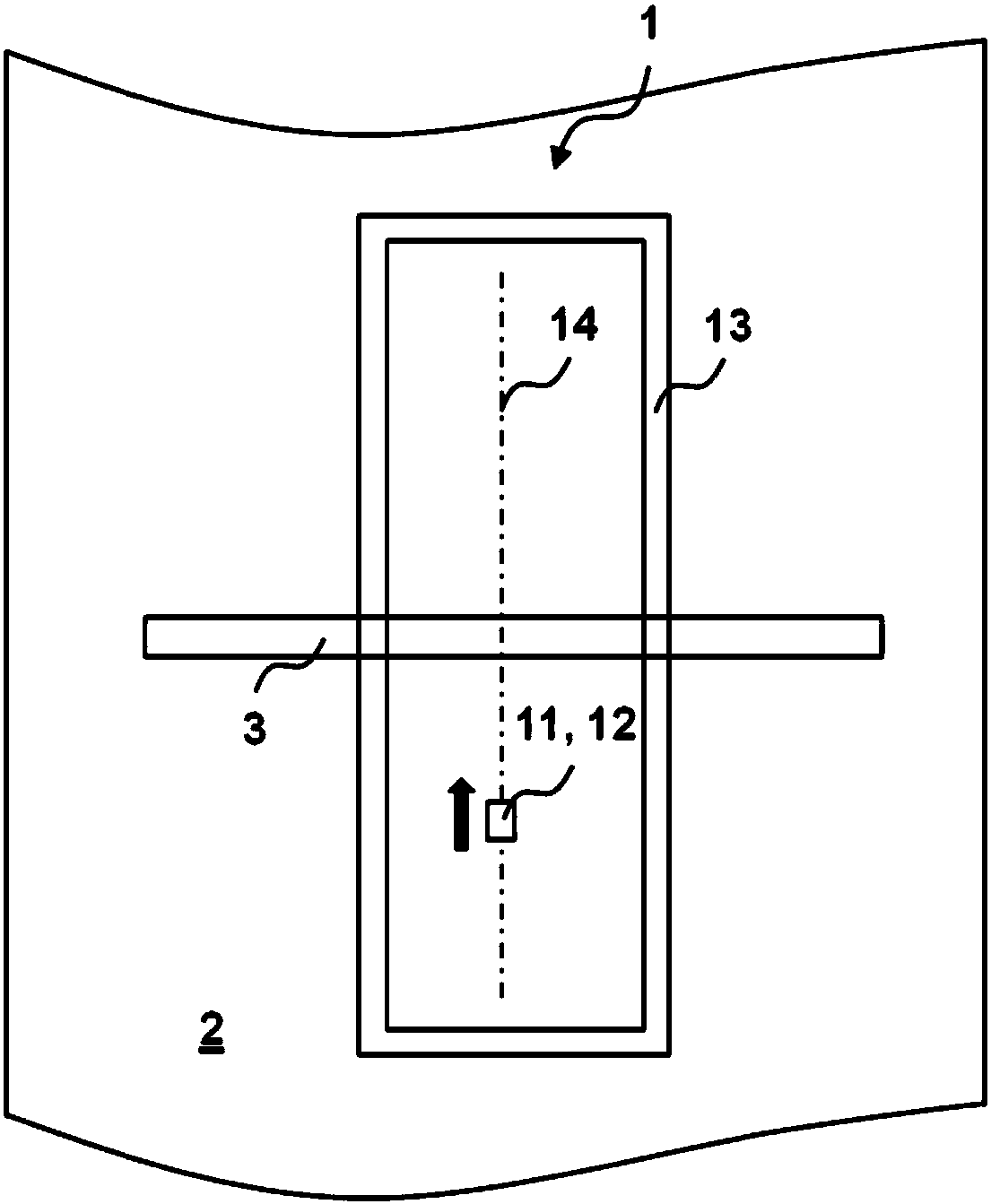
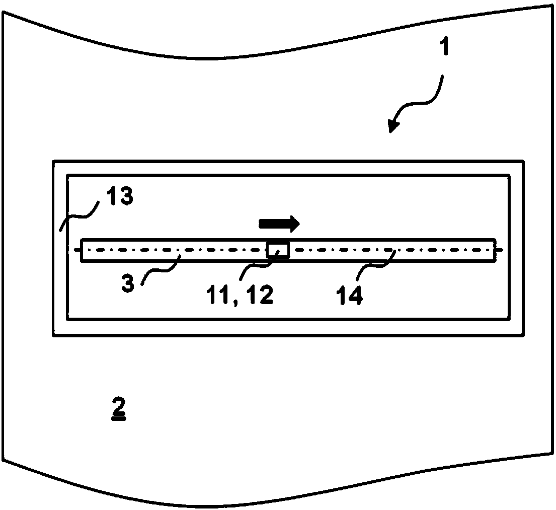
[0056] figure 1 and figure 2 Two schematic views of a preferred embodiment of a device 1 for calibrating a WIM sensor 3 installed in a roadway 2 are shown. On lane 2, the vehicle travels in or against the direction of travel. Driveway 2 has cladding. The coating consists of a mechanically resistant material such as asphalt, cement or the like.

[0057] Preferably, the WIM sensor 3 is a piezoelectric force transducer that emits an electrical signal proportional to the magnitude of the detected gravity. The WIM sensor 3 has a plurality of piezoelectric receiver elements in the sensor longitudinal direction, which are preferably arranged at a distance of 80 mm to 120 mm from one another. Preferably, the detection of gravity is performed with a temporal resolution of less than 1 kHz. The electrical signals are transmitted to the evaluation unit 4 and analyzed there. This is based on Figure 9 A schematic diagram of the device 1 is shown.

[0058] The WIM sensor 3 is locat...


PUM


Abstract

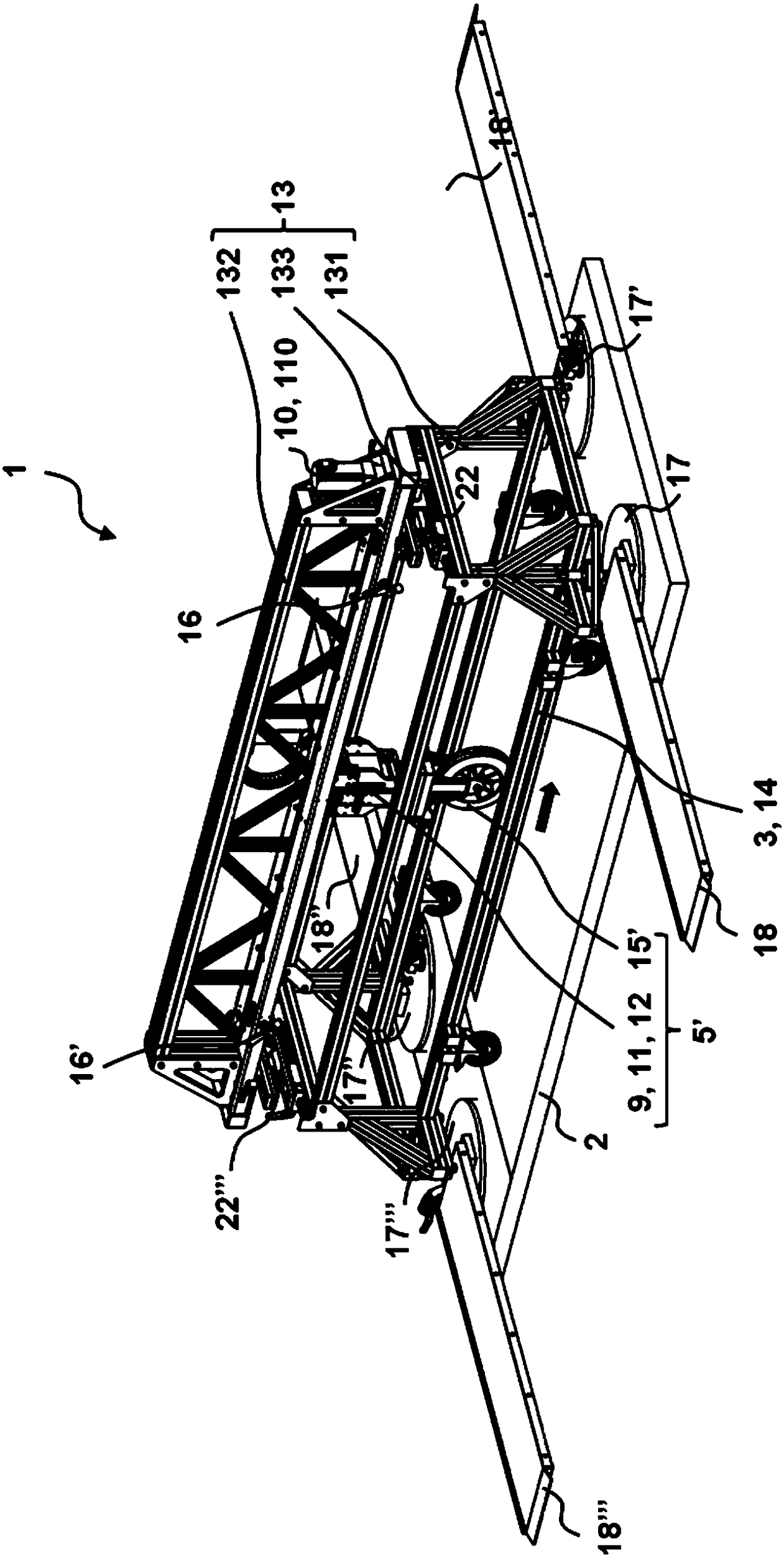
The invention relates to a device (1) for calibrating a Weigh-In-Motion (WIM) sensor (3) installed in a roadway (2); which device (1) has at least one force sensor (12), which force sensor (12) detects a reference force with which reference force of the WIM sensor (3) can be calibrated; which device (1) has an applicator (15-15 "), with which applicator (15-15") the reference force can be introduced into the carriageway (2); wherein the device (1) comprises an actuator (11), which actuator (11) generates the reference force; and wherein the actuator (11), force sensor (12) and applicator (15-15 ") are mechanically interconnected and form a vehicle (5-5").

Description

technical field [0001] The invention relates to a device for calibrating a weigh-in-motion (WIM) sensor. The invention also relates to a method for calibrating a WIM sensor. Background technique [0002] A WIM sensor is a force sensor that can be installed in a roadway. With such a WIM sensor installed in a roadway, the gravity of a vehicle driving on the roadway can be detected. Various traffic information can be determined from the detected gravity, such as wheel loads, axle loads, total weight, tire pressure of the moving vehicle. WIM sensors are typically piezoelectric force transducers that detect the gravitational force of a vehicle passing the WIM sensor at normal driving speeds. The piezoelectric force transducer emits an electrical signal proportional to the magnitude of the detected gravitational force, which is transmitted to the evaluation unit and evaluated there. Therefore, the WIM sensor and the analysis unit form a system for automatic detection of traffi...

Claims


Application Information

Patent Timeline
Patent Type & Authority Applications(China)
IPC IPC(8): G01G23/01
CPCG01G23/01G01G19/024G01G21/26E01F11/00G01G19/02G01G19/00G01G3/13G01G19/035
Inventor T·伍霍曼A·霍夫曼M·埃施巴赫尔
Owner KISTLER HLDG AG
Learn More