
Improved-type energy-saving and power-saving control device used for enterprises

An energy-saving control and improved technology, which is applied in the direction of connecting/disconnecting connected parts, coupling devices, parts of connecting devices, etc., can solve problems such as waste, forgetting to turn off power, hidden safety hazards, etc., and achieve convenient operation, The effect of simple structure

Inactive Publication Date: 2018-09-07
佛山诗勤智能科技有限公司
View PDF0 Cites 4 Cited by
  • Summary
  • Abstract
  • Description
  • Claims
  • Application Information

AI Technical Summary

Problems solved by technology

[0002] At present, many enterprises will use large warehouses, which need to use a lot of lighting or other electrical equipment, but it often happens that workers leave work but forget to turn off the power, which causes unnecessary waste of electricity, especially In some warehouses that no one has entered for a long time, there is a lot of unnecessary waste, and there are also great potential safety hazards. Therefore, a design is designed to be installed on the gate of the warehouse or office building, and then automatically cut off when passing through the extrusion of the door. An improved energy-saving and energy-saving control device for enterprises to open the circuit is really necessary

Method used


Image

  • Improved-type energy-saving and power-saving control device used for enterprises
  • Improved-type energy-saving and power-saving control device used for enterprises
  • Improved-type energy-saving and power-saving control device used for enterprises

Examples


Embodiment Construction

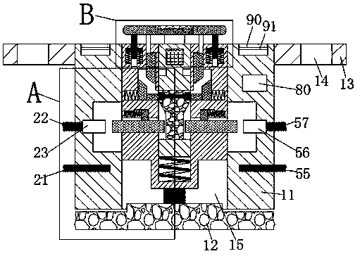
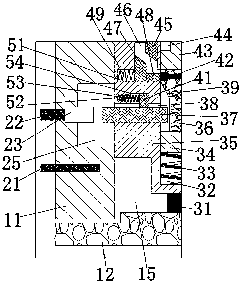
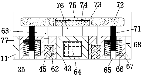
[0017] Such as Figure 1-Figure 5As shown, an improved energy-saving and power-saving control device for enterprises of the present invention includes a device main body 11, an electrification device installed in the device main body 11, and a locking device installed in the device main body 11. device, the energization device includes a main chamber 15 arranged up and down through the device main body 11, and the left and right symmetry of the main chamber 15 is arranged in the main chamber 15 and communicated with the main chamber 15. Through cavity 25, on the left inner wall of said through cavity 25 on the left side, there is fixedly provided a live wire power-in connector 23, the left end of said live wire power-in connector 23 is fixedly connected with a wire located in the main body 11 of the device and has one end extending out of the said device main body 11. The live wire input wire 22 outside the left end surface of the device main body 11, and the live wire outlet ...


PUM


Abstract

The present invention discloses an improved-type energy-saving and power-saving control device used for enterprises. The device comprises a device main body, an electrifying device arranged in the device main body and a locking device arranged in the device main body. The electrifying device comprises a main cavity, wherein the main cavity penetrates the device main cavity from top to bottom. Theleft side and the right side of the main cavity are symmetrically provided with through cavities, wherein each through cavity is arranged in the main cavity, and each through cavity is interlinked with the main cavity. The left inner wall of the through cavity on the left side is fixedly provided with a live-wire power-inputting connector, and the left end of the live-wire power-inputting connector is fixedly connected with a live-wire power-inputting wire, wherein the live-wire power-inputting wire is located in the device main body, and one end of the live-wire power-inputting wire extends out of the left end surface of the device main body. The right inner wall of the through cavity on the right side is fixedly provided with a live-wire power-outputting connector, and the right end of the live-wire power-outputting connector is fixedly connected with a live-wire power-outputting wire, wherein the live-wire power-outputting wire is located in the device main body, and one end of thelive-wire power-outputting wire extends out of the right end surface of the device main body.

Description

technical field [0001] The invention relates to the technical field of energy saving and electricity saving, in particular to an improved energy saving and electricity saving control device for enterprises. Background technique [0002] At present, many enterprises will use large warehouses, which need to use a lot of lighting or other electrical equipment, but it often happens that workers leave work but forget to turn off the power, which causes unnecessary waste of electricity, especially In some warehouses that no one has entered for a long time, there is a lot of unnecessary waste, and there are also great potential safety hazards. Therefore, a design is designed to be installed on the gate of the warehouse or office building, and then automatically cut off when passing through the extrusion of the door. An improved energy-saving and power-saving control device for enterprises that open the circuit is really necessary. Contents of the invention [0003] The technical...

Claims


Application Information

Patent Timeline
Patent Type & Authority Applications(China)
IPC IPC(8): H01R13/713H01R13/639H01R13/62
CPCH01R13/713H01R13/6205H01R13/639
Inventor 肖小玉
Owner 佛山诗勤智能科技有限公司
Learn More