
An automatic dipping equipment for fixture production

A fixture and equipment technology, applied in the field of automatic dip molding equipment for fixture production, can solve problems such as low dip molding production efficiency, and achieve the effects of improving stability and safety, high degree of automation, and synchronous and efficient transfer.

Active Publication Date: 2019-10-15
阜阳汇中芯自动化技术有限公司
View PDF5 Cites 0 Cited by
  • Summary
  • Abstract
  • Description
  • Claims
  • Application Information

AI Technical Summary

Problems solved by technology

[0004] The purpose of the present invention is to address the deficiencies of the prior art, to provide an automatic plastic dipping equipment for fixture production, which drives the clamping assembly to clamp the parts to be dipped by the transfer mechanism while rotating, so as to realize two different production tools Fast automatic transfer; Solve the technical problem of low production efficiency of dipping in the existing technology

Method used


Image

  • An automatic dipping equipment for fixture production
  • An automatic dipping equipment for fixture production
  • An automatic dipping equipment for fixture production

Examples


Embodiment 1

[0033] Embodiments of the present invention are described in detail below, examples of which are shown in the drawings, wherein the same or similar reference numerals designate the same or similar elements or elements having the same or similar functions throughout. The embodiments described below by referring to the figures are exemplary and are intended to explain the present invention and should not be construed as limiting the present invention.

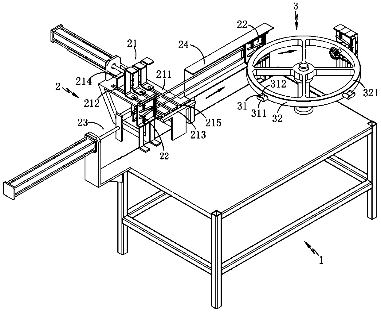
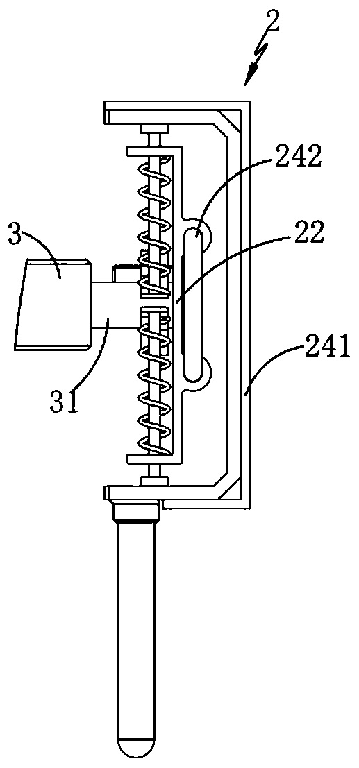
[0034] Such as figure 1 , 2 As shown in and 3, an automatic dipping equipment for fixture production, including frame 1, also includes:

[0035] Feeding mechanism 2, the feeding mechanism 2 is arranged on the frame 1, which respectively includes a batching assembly A21 for transferring the parts to be dipped, a clamping assembly 22 for fixing the parts to be dipped, and a The batching assembly B23 conveyed by the clamping assembly 22 and the limiting assembly 24 for limiting and guiding the clamps and tooling; structure; and ...

Embodiment 2

[0041] Such as figure 1 with 6 As shown, the parts that are the same as or corresponding to those in Embodiment 1 adopt the reference numerals corresponding to Embodiment 1. For the sake of simplicity, only the differences between Embodiment 1 and Embodiment 1 are described below; the differences between Embodiment 2 and Embodiment 1 The difference is that: the guide rod 242 is fixedly arranged on the frame 1, one end of which extends outside the limiting groove 241, and forms a gap between the feeding part 231 and the clamping assembly 22. The loading space 240; the clamping assembly 22 is positioned by the guide rod 242 extending to the outside of the limiting groove 241, so as to realize the partition entry of the two production materials and the subsequent synchronous transfer, thereby realizing the orderly and stable operation of the present invention.

[0042] Further, as figure 1 , 3 , 7, 8 and 9, the clamping assembly 22 is inside the part to be impregnated, which i...


PUM


Abstract

The invention relates to the technical field of dip-coating production, in particular to automatic dip-coating equipment used for clamp production. The equipment comprises a rack, a loading mechanismand a transferring mechanism, wherein the loading mechanism comprises a distribution assembly A for transferring a part to be subjected to dip-coating, a clamping assembly, a distribution assembly B and a limiting assembly for conducting limiting and guiding on clamps and frocks; the transferring mechanism is located on the next station of the loading mechanism and located on one side of the loading mechanism and comprises a connection assembly which is matched with the clamping assembly and used for driving the clamping assembly to tightly clamp the part to be subjected to dip-coating and a rotating assembly driving the connection assembly to conduct station transferring, and in the process that the connection assembly is driven by the rotating assembly to move, through a connection blockarranged on the connection assembly, the clamp assembly is driven to move and to fix and clamp the part about to be subjected to dip-coating. The transferring mechanism rotates while driving the clamp assembly to clamp tightly the part about to be subjected to dip-coating, so that fast automatic transferring of the two different production cools is achieved; the technical problem that in the prior art, the dip-coating production efficiency is low is solved.

Description

technical field [0001] The invention relates to the technical field of plastic dipping production, in particular to an automatic plastic dipping equipment for fixture production. Background technique [0002] Plastic dipping is a plastic coating process, which can be divided into liquid dipping and powder dipping according to the raw materials of dipping. Molding (vibration, removing excess powder) → curing (180°C-200°C for 10 minutes) → lowering the workpiece. During immersion, the heated metal sticks to the surrounding material, the hotter the metal, the longer the immersion time and the thicker the material. Naturally, temperature and dip profile are key factors in determining how much plastisol sticks. [0003] Most of the liquid dipping adopts hot dipping liquid, and the thermoplastic coating film has the characteristics of softening when exposed to heat and solidifying to form a film after cooling. Especially for some dipping parts that need to be fixed and clamped ...

Claims


Application Information

Patent Timeline
Patent Type & Authority Patents(China)
IPC IPC(8): B05C3/10B05C13/02
Inventor 李重重李开奇李孟鹏
Owner 阜阳汇中芯自动化技术有限公司
Learn More