Auxilary device for casting mould

An auxiliary device and casting mold technology, applied in the field of casting, can solve the problems of high defect rate and heavy repair workload, etc., and achieve the effects of improving yield, strengthening feeding and compact structure

Pending Publication Date: 2018-09-11
上海中振有色金属铸造有限公司
View PDF6 Cites 4 Cited by
  • Summary
  • Abstract
  • Description
  • Claims
  • Application Information

AI Technical Summary

Problems solved by technology

[0006] The purpose of the present invention is to overcome the deficiencies of the prior art, to provide an auxiliary device for casting molds that vibrates in the left and right directions during the pouring process, and solves the problem of high defective rate when cooling the existing castings and heavy repairing workload.

Method used


Image

  • Auxilary device for casting mould
  • Auxilary device for casting mould

Examples


Embodiment 1

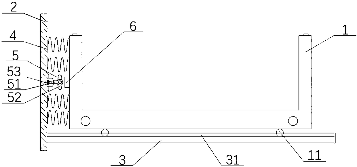
[0028] like Figure 1 ~ Figure 2 The auxiliary device for casting mold shown includes a box body 1 for placing a casting box, a baffle plate 2 and a bottom plate 3, the bottom plate 3 is provided with a chute 31, and the bottom of the box body 1 is provided with a pulley 11 , the pulley 11 slides in the chute 31 so that the box body 1 is slidably connected with the bottom plate 3;

[0029] The baffle plate 2 is arranged on one side of the bottom plate 3, and the baffle plate 2 protrudes a vibrating spring 4 and a telescopic member 5 laterally toward the box body 1, and the other end of the vibrating spring 4 is installed on the box body 1, the telescopic member 5 abuts against the box body 1 intermittently, and the minimum length of the vibrating spring 4 when compressed > the minimum length of the telescopic member 5 when contracted.

[0030] The telescopic member 5 includes a mount 51 arranged on the baffle 2 , a cam 52 and a drive motor 53 arranged on the mount 51 ;

[00...


PUM


Abstract

The invention relates to the technical field of casting, in particular to an auxilary device for a casting mould. The auxilary device comprises a box body used for containing a casting box, a baffle and a bottom plate, wherein a sliding chute is formed in the bottom plate, pulleys are arranged at the bottom of the box body, and the pulleys slide in the sliding chute so that the box body can be insliding connection with the bottom plate; the baffle is arranged on one side of the bottom plate; the baffle stretches out transversely in the direction of facing the box body, forming a vibrating spring and a telescopic part; and the other end of the vibrating sprign is installed on the box body, the telescopic part abuts against the box body intermittently, the minimum length of the vibrating spring during compression is larger than that of the telescopic part during contraction. The auxilary device has the benificial effects that in the pouring process, left-anf-right direction vibration isprovided for a pouring mold, and the problems of a high defect rate and a heavy repair workload during cooling of an existing casting are solved.

Description

technical field [0001] The invention relates to the technical field of casting, in particular to an auxiliary device for a casting mold. Background technique [0002] In the production of casting, the method of pouring hard sand molds into boxes is often used. First, the casting box is placed on the casting platform, and then it is gradually cooled naturally. During the static cooling and solidification process of liquid metal, due to the gradually large difference in overall wall thickness, conventional processes are difficult to ensure overall balanced cooling, and defects such as cracks, shrinkage porosity, shrinkage cavities, slag inclusions, and coarse grains are prone to occur locally, especially It is a large steel casting. After non-destructive testing, the casting defect is particularly prominent. The workload of welding repair is heavy, which virtually increases the production cost. [0003] After a long period of practice, it is found that if the liquid metal is ...

Claims


Application Information

Patent Timeline
Patent Type & Authority Applications(China)
IPC IPC(8): B22D27/08
CPCB22D27/08
Inventor 朱月中
Owner 上海中振有色金属铸造有限公司
Why Eureka
Try Eureka