Oil heating and heat recovering reaction pot

An oil heating and heat recovery technology, which is applied in heat exchanger types, lighting and heating equipment, chemical/physical/physicochemical fixed reactors, etc., can solve the problem of bulky reaction pots, waste of energy, and increased risk of use, etc. problem, to achieve the effect of improving cooling effect, increasing heating efficiency, and improving heat exchange rate

Inactive Publication Date: 2006-05-17
劳关明
View PDF0 Cites 4 Cited by
  • Summary
  • Abstract
  • Description
  • Claims
  • Application Information

AI Technical Summary

Problems solved by technology

The disadvantage is that due to the double-layer structure, the reaction pot is bulky, and the larger the volume, the greater the pressure on the inner wall, which increases the risk of product use.
At the same time, when the mixed liquid is cooled, the temperature of the discharged cooling water is also high due to the high temperature of the mixed liquid at first, and as the temperature of the mixed liquid decreases, the temperature of the discharged cooling water also gradually decreases, and the high temperature cooling water and Low-temperature cooling water is discharged in the same water pipe, wasting a certain amount of energy

Method used


Image

  • Oil heating and heat recovering reaction pot
  • Oil heating and heat recovering reaction pot
  • Oil heating and heat recovering reaction pot

Examples


Embodiment 1

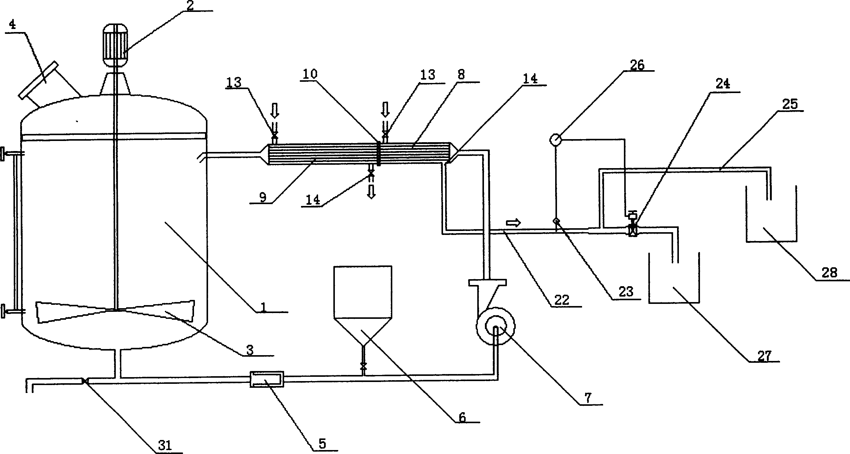
[0022] Embodiment 1: as figure 1 As shown, the present invention includes a pot body 1 and a motor 2. A stirrer 3 connected to the motor 2 is provided in the pot body 1, and an inlet and outlet 4 is provided on the upper side of the pot body 1. The pot body 1 is a single-layer The structure is connected with the filter 5 and the liquid supply and discharge valve 31 respectively through pipelines, and the other end of the filter 5 is connected with the feeding barrel 6 and the circulating water pump 7 through pipelines. There is a flange 10 connected between the pot body 1 and the circulating water pump 7 The water cooling exchanger 8 and the oil heating exchanger 9 combined into one.

[0023] Such as Figure 5 As shown, the water cooling exchanger 8 and the oil heating exchanger 9 have the same structure, and both include a cylinder 16, which is provided with layered heat receiving tubes 11, and the heating tubes 11 can be metal round tubes or special-shaped tubes with high h...

Embodiment 2

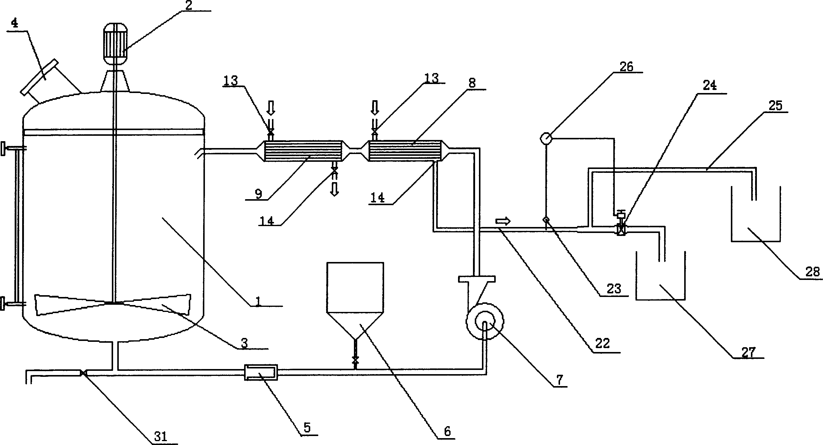
[0029]Embodiment 2: The basic structure of this embodiment is the same as that of Embodiment 1, except that a water cooling exchanger 8 and an oil heating exchanger 9 connected in series are connected between the pot body 1 and the circulating water pump 7, such as figure 2 , Figure 6 shown. Its working process is with embodiment 1.

Embodiment 3

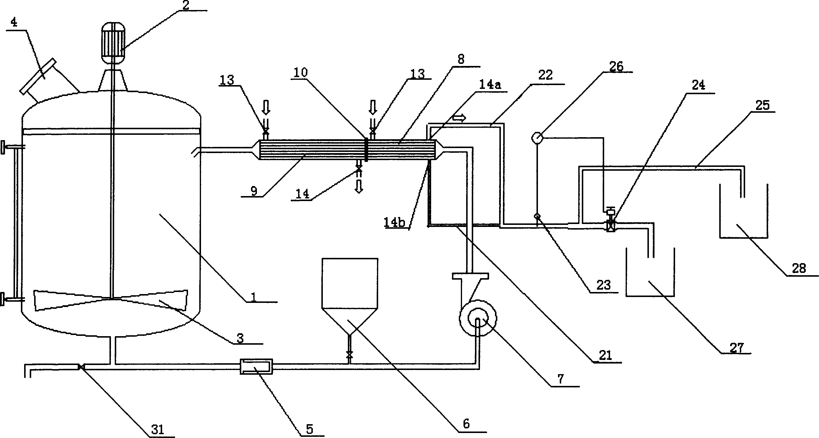
[0030] Embodiment 3: The basic structure of this embodiment is the same as that of Embodiment 1, except that the outlet 14 provided on the cylinder 16 of the water cooling exchanger 8 can be divided into a main outlet 14a and a secondary outlet 14b, wherein the main outlet 14a Located above the cylinder 16, the auxiliary outlet 14b is located below the cylinder 16, and the diameter of the auxiliary outlet 14b is smaller than that of the main outlet 14a. The main outlet 14a is connected with a pipe 22 , the auxiliary outlet 14b is connected with a pipe 21 , and the other end of the pipe 21 communicates with the pipe 22 . Such as image 3 , Figure 5 shown. The working process of this embodiment is the same as that of Embodiment 1, the difference is that when the cooling water is discharged, it can flow out from the main outlet 14a with a large flow rate, and flow out from the auxiliary outlet 14b with a small flow rate, and then divert to the diversion device after being aggr...


PUM


Abstract

The present invention discloses one kind of oil heating and heat recovering reaction pot, and belongs to the field of chemical material processing apparatus technology. The oil heating and heat recovering reaction pot includes a pot body, a filter and a circulating water pump connected successively, as well as combined or serially connected water cooling heat exchanger with shunt and oil heating heat exchanger connected between the pot body and the circulating water pump. By means of the water cooling heat exchanger and the oil heating heat exchanger, the mixed liquid may be cooled and heated to the required temperature, and the water exhausted from the heat exchanger may be made to flow into the hot water or cold water returning unit to utilize the heat energy fully.

Description

technical field [0001] The invention discloses an oil heating and heat recovery type reaction pot, which belongs to the technical field of chemical raw material processing equipment. Background technique [0002] The reaction pot is used in the chemical industry to stir a variety of chemical raw materials to cause chemical or physical reactions, and at the same time, it can be heated or cooled according to the needs of the process. At present, the commonly used reaction pot is a double-layer structure, that is, there is an interlayer outside the pot body. When the chemical raw materials are stirred and the mixed liquid needs to be heated or cooled, the interlayer is filled with steam or cooling water to heat up or cool down. The disadvantage is that due to the double-layer structure, the volume of the reaction pot is huge, and the greater the volume, the greater the pressure on the inner wall, which increases the danger of product use. At the same time,...

Claims


Application Information

Patent Timeline
Patent Type & Authority Applications(China)
IPC IPC(8): B01J19/00B01F15/06
CPCB01J19/0013B01J19/1881B01J2219/0011F28D7/0066F28D7/0091F28D7/1607B01F25/51B01F27/80B01F35/92B01J19/18F28F9/26B01F25/52B01F25/53
Inventor 劳关明王雁峰王金昌钟立敏劳秋明卜阿金
Owner 劳关明
Why Eureka
Try Eureka