
Grinding machine used for optical fiber end surface grinding

A technology of optical fiber end face and grinding machine, which is applied in the field of grinding machine, can solve the problems of grinding quality and efficiency reduction, and achieve the effect of improving efficiency and not easy to drop

Inactive Publication Date: 2018-09-11
王丽
View PDF9 Cites 2 Cited by
  • Summary
  • Abstract
  • Description
  • Claims
  • Application Information

AI Technical Summary

Problems solved by technology

[0002] Optical fiber, short for optical fiber, is a light transmission tool that utilizes the principle of total reflection of light in fibers made of glass or plastic. Optical fiber was invented by Kao Kung, the former president of the Chinese University of Hong Kong. The tiny optical fiber is packaged in Usually, the transmitting device at one end of the fiber uses a light-emitting diode or a laser beam to transmit light pulses to the fiber, and the receiving device at the other end of the fiber uses a photosensitive element to detect the pulse. In daily life, because the transmission loss of light in optical fibers is much lower than that of electricity in wires, optical fibers are used for long-distance information transmission; most of the current market uses manual grinding, and the grinding quality and efficiency are greatly reduced.

Method used


Image

  • Grinding machine used for optical fiber end surface grinding
  • Grinding machine used for optical fiber end surface grinding
  • Grinding machine used for optical fiber end surface grinding

Examples


Embodiment Construction

[0021] The following will clearly and completely describe the technical solutions in the embodiments of the present invention with reference to the accompanying drawings in the embodiments of the present invention. Obviously, the described embodiments are only some, not all, embodiments of the present invention. Based on the embodiments of the present invention, all other embodiments obtained by persons of ordinary skill in the art without making creative efforts belong to the protection scope of the present invention.

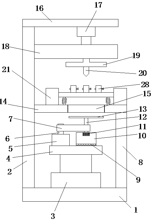
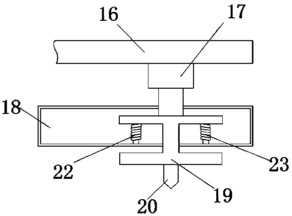
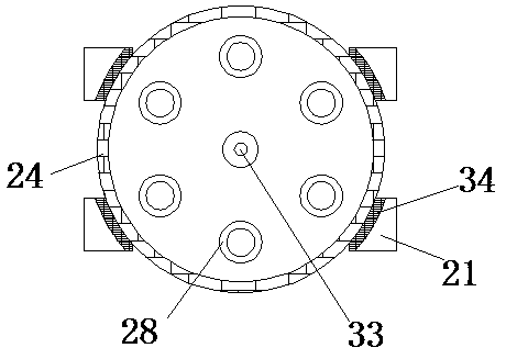
[0022] Embodiments of the present invention provide a grinding machine for optical fiber end face grinding, such as Figure 1-5 As shown, including the base 1, the left side of the top of the base 1 is fixedly installed with a support column 2, the top of the support column 2 is fixedly installed with a beam 16, and the bottom of the beam 16 is fixedly installed with an extrusion electric push rod 17, and the extrusion electric push rod The bottom of 17 is pro...


PUM


Abstract

The invention provides a grinding machine used for optical fiber end surface grinding, and relates to the field of optical fibers. The grinding machine comprises a base, wherein a supporting column isfixedly mounted at the left side of the top of the base; a beam is fixedly mounted on the top of the supporting column; the bottom of the beam is fixedly equipped with an extruding electric pushing rod; a spring box is arranged below the extruding elastic pushing rod; and a grinding table electric pushing rod is fixedly mounted in the middle of the top of the base. According to the grinding machine used for optical fiber end surface grinding provided by the invention, the grinding table electric pushing rod is arranged, so that a grinding table can move up and down; the spring box is matchedwith a first return spring and a second return spring, so that auxiliary return after extrusion of an extruded body is completed; and the springs are arranged, so that auxiliary return after extrusionof fixators is completed; the extruded body is matched with an extrusion cone, so that fixator plates are fixed during grinding; and the fixators are arranged, so that multiple optical fiber end surfaces can be grinded at the same time, and therefore, efficiency is improved.

Description

technical field [0001] The invention relates to the technical field of optical fiber processing, in particular to a grinding machine for optical fiber end face grinding. Background technique [0002] Optical fiber, short for optical fiber, is a light transmission tool that utilizes the principle of total reflection of light in fibers made of glass or plastic. Optical fiber was invented by Kao Kung, former president of the Chinese University of Hong Kong. The tiny optical fiber is packaged in Usually, the transmitting device at one end of the fiber uses a light-emitting diode or a laser beam to transmit light pulses to the fiber, and the receiving device at the other end of the fiber uses a photosensitive element to detect the pulse. In daily life, because the transmission loss of light in optical fibers is much lower than that of electricity in wires, optical fibers are used for long-distance information transmission; most of the current market uses manual grinding, and the ...

Claims


Application Information

Patent Timeline
Patent Type & Authority Applications(China)
IPC IPC(8): B24B37/10B24B37/30B24B37/34B24B41/00G02B6/25
Inventor 王丽
Owner 王丽
Learn More