
Light guide plate and backlight module

A technology of backlight module and light guide plate, which is applied in the field of backlight, can solve problems such as uneven luminous chromaticity, spectral absorption of glass light guide plate, difficulty in meeting the processing requirements of thinner and thinner backlight module, and achieve uniform luminous chromaticity and improved The effect of light guide effect

Pending Publication Date: 2018-09-11
CHANGZHOU ALMADEN
View PDF12 Cites 0 Cited by
  • Summary
  • Abstract
  • Description
  • Claims
  • Application Information

AI Technical Summary

Problems solved by technology

Usually, the light guide plate is made of acrylic material, but because of its low strength, it is often thick when used as a light guide plate, which is difficult to meet the processing requirements of light and thin backlight modules. In order to solve this problem, the light guide plate made of acrylic material is gradually replaced , Thin glass light guide plate instead, but the glass light guide plate absorbs the spectrum seriously, resulting in uneven luminous chromaticity and poor light guide effect

Method used


Image

  • Light guide plate and backlight module
  • Light guide plate and backlight module

Examples


Embodiment 1

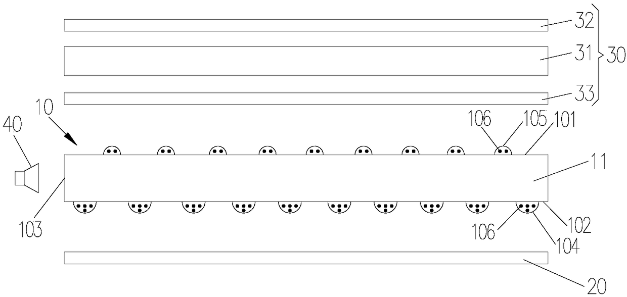
[0021] see figure 1 Embodiment 1 of the present invention provides a backlight module, the backlight module includes a light guide plate 10, a reflection plate 20 located below the light guide plate 10, a diffusion assembly 30 located above the light guide plate 10, and a Blue LED light source 40 . When in use, the light emitted by the blue LED light source 40 passes through the light guide plate 10 and then exits from the upper surface of the light guide plate 10 , and finally exits through the diffusion assembly 30 .

[0022] Specifically, the light guide plate 10 includes a base body 11, and the base body 11 is a glass plate. The substrate 11 has an upper surface 101, a lower surface 102 and a side surface 103, wherein the upper surface 101 and the lower surface 102 are arranged opposite to each other, the side surface 103 is located between the upper surface 101 and the lower surface 102, and the side surface 103 is used as the light incident surface of the substrate 11 ...

Embodiment 2

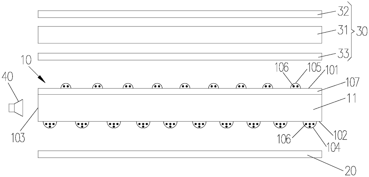
[0032] see figure 2 The difference between the light guide plate 10 provided in Embodiment 2 of the present invention and the light guide plate 10 in Embodiment 1 is that: a dielectric layer 107 is provided on the upper surface 102 of the substrate 11, and phosphor dots 105 are provided on the upper surface of the dielectric layer 107. The refractive index of the medium layer 107 is smaller than that of the substrate 11 and larger than that of air. In this embodiment, the medium layer 107 is an oil film. Therefore, when the excitation light is emitted from the upper surface 102 of the substrate 11 and the dielectric layer 107 in sequence, it can ensure that the light is emitted from the upper surface of the dielectric layer 107 as much as possible, so that the light is more concentrated.

[0033] Embodiment 2 of the present invention also provides a backlight module with the light guide plate 10 . Other structures in the backlight module are the same as those in Embodiment 1...


PUM


Abstract

The invention discloses a light guide plate which comprises a base body, wherein the base body is provided with an upper surface and a lower surface opposite to each other; the upper surface serves asa light-exiting surface of the base body; printing ink net points are arranged on the lower surface; fluorescent powder net points are arranged on the upper surface; the printing ink net points and the fluorescent powder net points are arranged in a staggered manner; fluorescent powder is arranged on the printing ink net points and the fluorescent powder net points; and the fluorescent powder isexcited by blue light. According to the light guide plate provided by the invention, excited light reflected for many times is ejected from the upper surface of the base body, so that the excited light can be fully excited by the fluorescent powder, and therefore, the light-emitting chromaticity is uniform, and the light guide effect is improved. The invention also provides a backlight module provided with the light guide plate.

Description

technical field [0001] The invention relates to the field of backlights, in particular to a light guide plate and a backlight module. Background technique [0002] The planar light guide plate is the main component of light transmission in the backlight module, and its light guide effect determines the uniformity and comfort of the emitted light. Usually, the light guide plate is made of acrylic material, but because of its low strength, it is often thick when used as a light guide plate, which is difficult to meet the processing requirements of light and thin backlight modules. In order to solve this problem, the light guide plate made of acrylic material is gradually replaced , Thin glass light guide plate instead, but the glass light guide plate absorbs the spectrum seriously, resulting in uneven luminous chromaticity and poor light guide effect. Contents of the invention [0003] The technical problem to be solved by the present invention is: in order to overcome the ...

Claims


Application Information

Patent Timeline
Patent Type & Authority Applications(China)
IPC IPC(8): F21S8/00F21V5/02F21V7/00F21V8/00F21Y115/10
CPCF21S8/00F21V5/02F21V7/00F21V2200/00F21Y2115/10
Inventor 初文静张喜强林俊良林金锡林金汉
Owner CHANGZHOU ALMADEN
Learn More