Communication pipe deformation monitoring device and method

A distance measuring device and pipeline technology, which is applied in the direction of measuring devices, optical devices, instruments, etc., can solve the problems of less manual monitoring techniques, laborious, fault point location, etc., to achieve stable and reliable measurement data, simple and reliable transmission structure, The effect of reducing the failure rate of equipment

Inactive Publication Date: 2018-09-11
LIAONING TECHNICAL UNIVERSITY
View PDF7 Cites 2 Cited by
  • Summary
  • Abstract
  • Description
  • Claims
  • Application Information

AI Technical Summary

Problems solved by technology

[0002] At present, manual monitoring of communication pipeline deformation is time-consuming and laborious, and it is impossible to realize real-time uninterrupted monitoring. It can only be inspected every once in a while; and there are few manual monitoring techniques and lack of corresponding instruments. early warning
In most cases, the communication line is passively maintained after the communication is interrupted, and it is basically impossible to realize the manual monitoring and early warning of the deformation of the communication pipeline
Because the material of the optical fiber itself is relatively brittle, the optical fiber is easily broken by external force when manually inspecting the line to find the fault location, so the deformation of the pipeline will easily cause the optical fiber to break and cause communication interruption. Immeasurable losses caused by communications, etc.
Under the existing technical conditions, if such a situation occurs, it is impossible to locate the fault point through technical means, and it can only be located manually, which wastes a lot of manpower, material and financial resources to find the fault, and takes a long time. The positioning and maintenance work has caused a lot of trouble. Once the communication optical cable fails, it will bring great losses to the communication security of the country and the people.

Method used


Image

  • Communication pipe deformation monitoring device and method
  • Communication pipe deformation monitoring device and method
  • Communication pipe deformation monitoring device and method

Examples


Embodiment Construction

[0020] In order to illustrate the present invention more clearly, the present invention will be further described below in conjunction with the accompanying drawings.

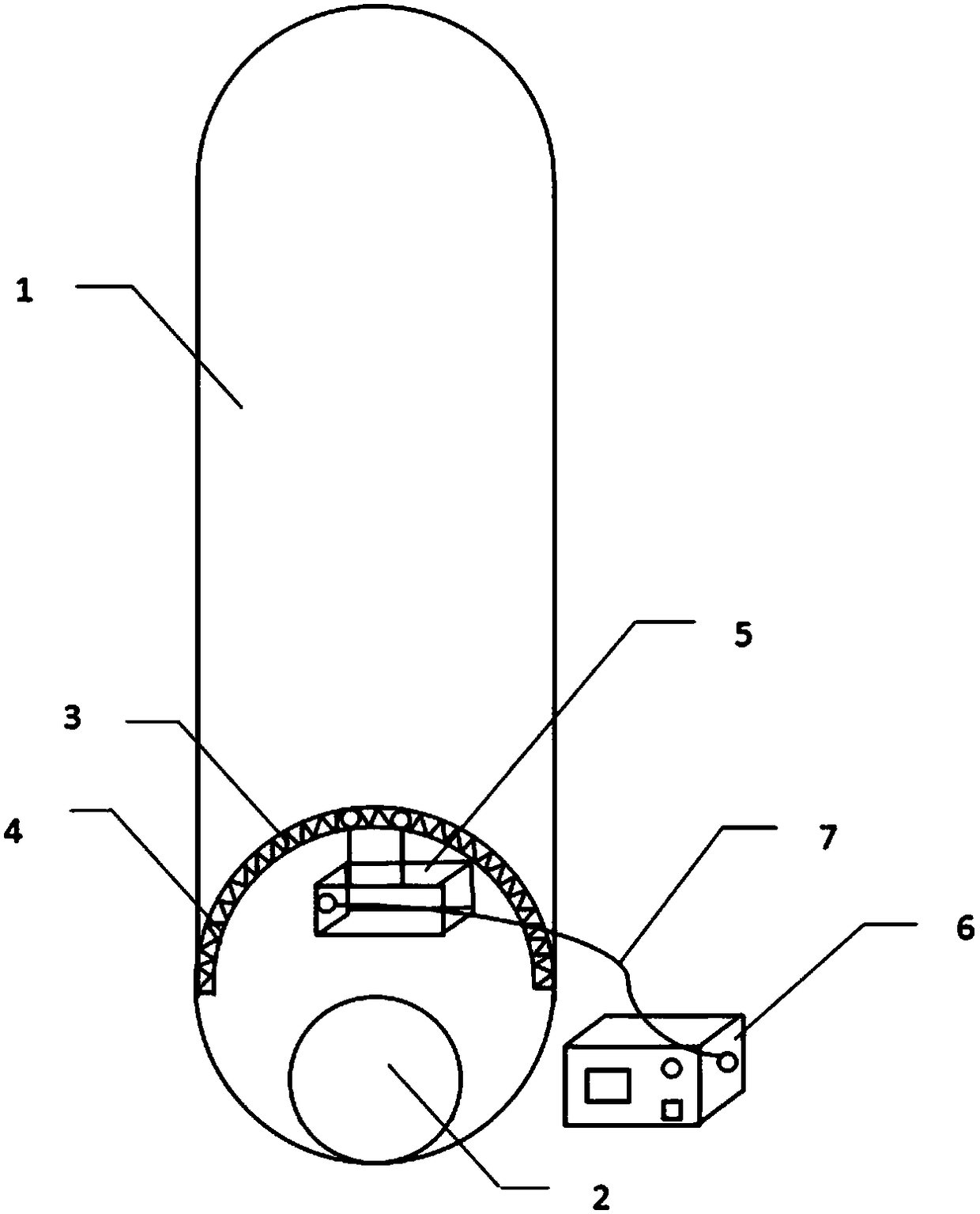
[0021] like figure 1 A communication pipeline deformation monitoring device shown includes: a distance measuring device 5 , a fan-shaped guide rail, and a main control device 6 . 2 is the optical fiber among the figure. The fan-shaped guide rail is installed along the inner wall at the mouth of the communication pipe, and the distance measuring device 5 is connected to the fan-shaped guide rail facing the inside of the pipe to measure the distance from the communication pipe mouth to the end of the communication pipe. The distance measuring device 5 can move along the fan-shaped guide rail. The distance measuring device and the main control Device 6 is connected.

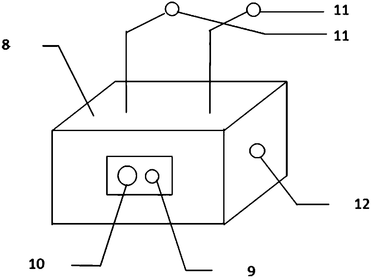
[0022] like figure 2 The distance measuring device 5 shown includes a laser range finder and a stepping motor, the laser range finder is divided...


PUM


Abstract

The invention provides a communication pipe deformation monitoring device and method. The device comprises a distance measuring apparatus, a fan-shaped guide rail and a main control apparatus. The fan-shaped guide rail is installed along the inner wall of the mouth of a communication pipe, and the distance measuring apparatus faces the interior of the pipe and is connected to the fan-shaped guiderail. The distance from the mount of the communication pipe to the tail end of the communication pipe is measured, and the distance measuring apparatus can move along the fan-shaped guide rail. The distance measuring apparatus is connected with a main control apparatus. A communication pipe deformation monitoring method comprises the steps: controlling a stepping motor to operate at a fixed time interval through the main control apparatus, driving the distance measuring apparatus to move from one end of the fan-shaped guide rail to the other end for one measurement; determining that there is no abnormality if the difference between the measured data and an initial value does not exceed a set threshold; determining that the abnormality happens if the differences between the measured data, obtained through three continuous measurements, and the initial value exceed the set threshold and the measured data obtained through three continuous measurements is the same, giving an alarm to an upper computer, and uploading the position of an abnormality. The measurement data is stable and reliable, and the method and device can achieve the direct early warning of the deformation trend.

Description

technical field [0001] The invention relates to the technical field of deformation measurement of communication pipes, in particular to a device and method for monitoring deformation of communication pipes. Background technique [0002] At present, manual monitoring of communication pipeline deformation is time-consuming and laborious, and it is impossible to realize real-time uninterrupted monitoring. It can only be inspected every once in a while; and there are few manual monitoring techniques and lack of corresponding instruments. Early warning. In most cases, the communication line is passively maintained after the communication is interrupted, and it is basically impossible to realize manual monitoring and early warning of the deformation of the communication pipeline. Because the material of the optical fiber itself is relatively brittle, the optical fiber is easily broken by external force when manually inspecting the line to find the fault location, so the deformati...

Claims


Application Information

Patent Timeline
Patent Type & Authority Applications(China)
IPC IPC(8): G01B11/16
Inventor 谢国民黄睿灵刘明雨刘宽
Owner LIAONING TECHNICAL UNIVERSITY
Why Eureka
Try Eureka