Novel laser engraving device

A new type of laser engraving technology, applied in the field of sheet metal processing, can solve the problems of affecting the accuracy of processing, affecting the accuracy of secondary processing, and difficult to effectively control the quality, and achieve the effect of preventing displacement and ensuring quality control.

Inactive Publication Date: 2018-09-14
王磊
View PDF0 Cites 5 Cited by
  • Summary
  • Abstract
  • Description
  • Claims
  • Application Information

AI Technical Summary

Problems solved by technology

[0002] At present, laser engraving is a technological revolution in sheet metal processing and is the core technology in sheet metal processing. Laser engraving machines have high flexibility, fast engraving speed, high production efficiency, short product production cycle, and high production quality. In the process of laser engraving, the maximum size, material, maximum thickness of the workpiece to be engraved and the size of the raw material format should be considered in the process of laser engraving. However, the current laser engraving machines on the market place the required workpiece on the workbench Engraving is carried out on the surface of the workbench. After the laser penetrates the workpiece, damage will be formed on the surface of the workbench, which affects the accuracy of the secondary processing, and greatly reduces the service life of the workbench and increases the processing cost. Moreover, the workpiece is not clamped Displacement is easy to occur under the condition of the machine, which affects the precision of processing, making it difficult to effectively control the quality during processing

Method used


Image

  • Novel laser engraving device
  • Novel laser engraving device
  • Novel laser engraving device

Examples


Embodiment Construction

[0013] The following will clearly and completely describe the technical solutions in the embodiments of the present invention with reference to the accompanying drawings in the embodiments of the present invention. Obviously, the described embodiments are only some, not all, embodiments of the present invention. Based on the embodiments of the present invention, all other embodiments obtained by persons of ordinary skill in the art without making creative efforts belong to the protection scope of the present invention.

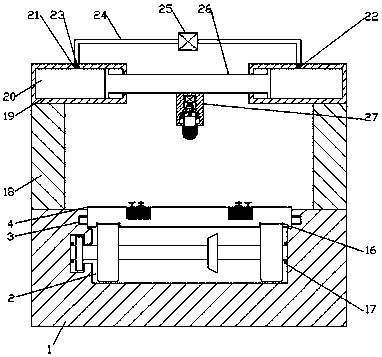
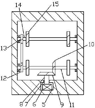
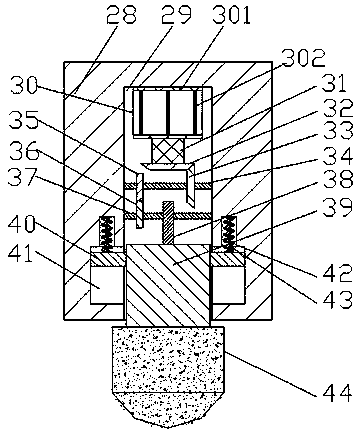
[0014] see Figure 1-4, an embodiment provided by the present invention: a new type of laser engraving device, including an assembly workbench 1, a rotating chamber 2 is arranged inside the assembly workbench 1, and the left and right ends of the upper end wall of the rotating chamber 2 are arranged symmetrically There is a sliding groove 3, the sliding groove 3 communicates with the rotating chamber 2 and the horizontal workbench 4, the horizontal workbench 4...


PUM


Abstract

The invention discloses a novel laser engraving device which comprises a horizontal worktable, wherein a rotating cavity is formed in the horizontal worktable; supporting rods are symmetrically arranged at the left and right ends of the upper end surface of a final assembly worktable, and the upper ends are connected between the supporting rods through a push rod in a hydraulic cavity through a fixed block; a lifting cutting device is mounted on the rod body of the push rod in a sleeving manner; a plurality of screw-up mechanisms and four same screw-up screws matched with the screw-up mechanisms in use are uniformly distributed in the middle position of the upper end surface of the worktable. During work, blank waste caused by displacement and processing failure when workpieces are processed by means of a clamping structure formed by a pressing spacer and a round supporting plate is avoided. A lifting cutting device shifts left and right through a hydraulic pump, so that the working point can be determined more accurately, the processing precision is improved. A rotating gear A and a gear slot are matched, so that the friction coefficient can be reduced.

Description

technical field [0001] The invention relates to the field of sheet metal processing, in particular to a novel laser engraving device. Background technique [0002] At present, laser engraving is a technological revolution in sheet metal processing, and is the core technology in sheet metal processing. Laser engraving machines have high flexibility, fast engraving speed, high production efficiency, short product production cycle, and high production quality, winning customers In the process of laser engraving, the maximum size, material, maximum thickness of the workpiece to be engraved and the size of the raw material format should be considered in the process of laser engraving. However, the current laser engraving machines on the market place the required workpiece on the workbench Engraving is carried out on the surface of the workbench. After the laser penetrates the workpiece, damage will be formed on the surface of the workbench, which affects the accuracy of the secon...

Claims


Application Information

Patent Timeline
Patent Type & Authority Applications(China)
IPC IPC(8): B23K26/362B23K26/70B23K37/04B23K26/08
CPCB23K26/083B23K26/0876B23K26/361B23K26/702B23K37/0435
Inventor 王磊
Owner 王磊
Why Eureka
Try Eureka