
Automatic material loading machine for plates

A technology for loading machines and plates, which is applied in the direction of grinding feed movement, grinding machine parts, metal processing equipment, etc., which can solve the problems of easy errors, increased safety accidents, and low safety, so as to reduce accidents incidence rate, reduce labor intensity, and improve work efficiency

Active Publication Date: 2018-09-14
山东信义汽车配件制造有限公司
View PDF7 Cites 2 Cited by
  • Summary
  • Abstract
  • Description
  • Claims
  • Application Information

AI Technical Summary

Problems solved by technology

[0002] When auto parts are processed, a series of mechanical processing methods such as turning, milling, grinding, forging, etc. are performed on the workpiece. As we all know, due to the late start and slow development of my country's modern industry, many parts processing enterprises have outdated equipment and low creativity. The processing method is relatively primitive and labor-intensive
At present, most workshops still use manual loading during production, and the equipment on the production line is generally bulky and heavy, with high risk
[0003] Generally, plates are used the most in parts processing. Manually take out the plates from the material box and directly operate them on the processing equipment, which has low safety and high labor intensity. Long-term fatigue increases, resulting in low work efficiency and easy operation. Cause mistakes and increase the probability of safety accidents

Method used


Image

  • Automatic material loading machine for plates
  • Automatic material loading machine for plates
  • Automatic material loading machine for plates

Examples


Embodiment Construction

[0029] In order to make the technical means, creative features, goals and effects achieved by the present invention easy to understand, the present invention will be further elaborated below.

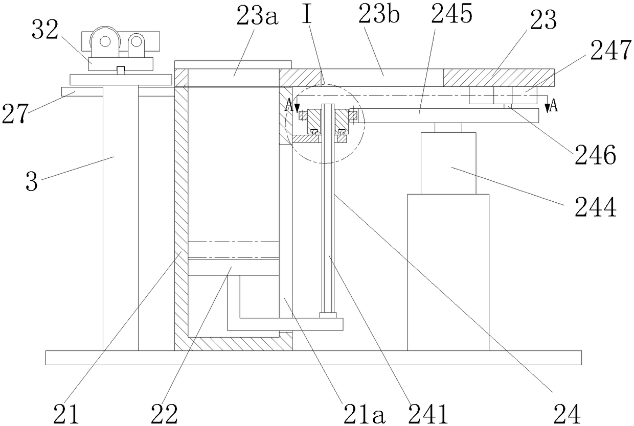
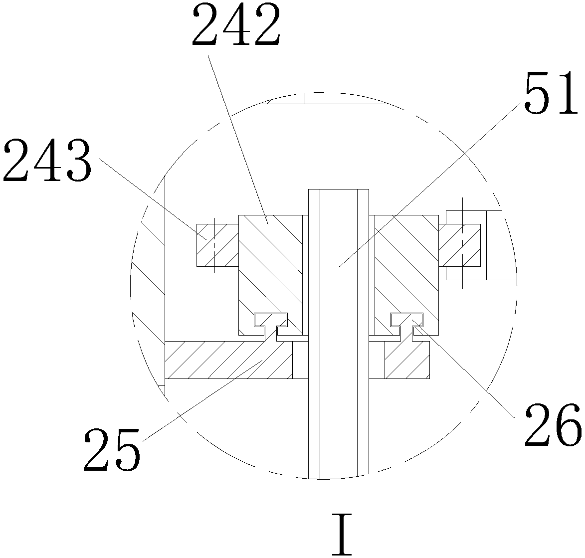
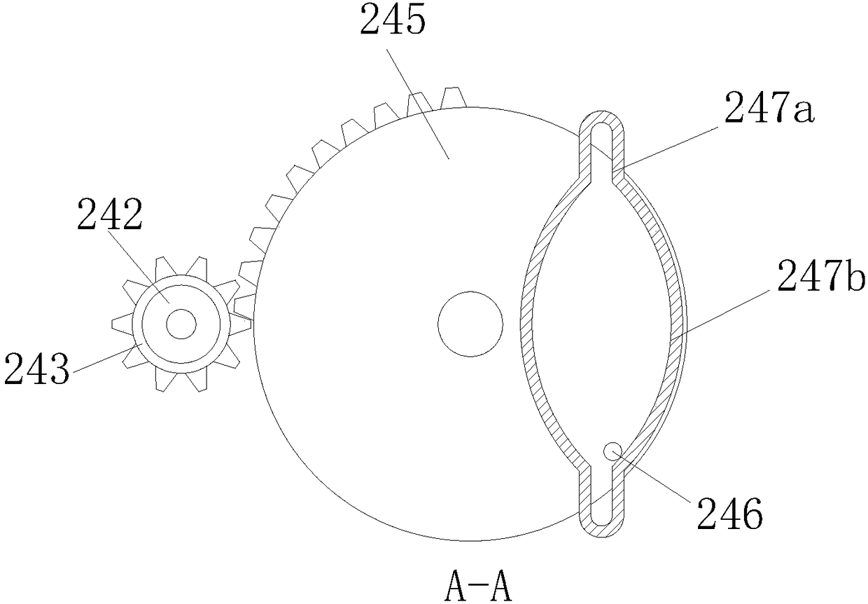
[0030] Such as Figure 1 to Figure 5 As shown, an automatic feeding machine for plates includes a bottom plate 1, the right side of the bottom plate 1 is provided with a retrieving mechanism 2 that pushes out the plates sequentially and outputs them intermittently, and the left side is provided with magnetic adsorption plates and the positioning distance Adjustable grabbing and discharging mechanism3.

[0031] The grasping and discharging mechanism 3 includes a pneumatic guide rail 31 fixed on the left front of the base plate 1, a slider 32 installed on the pneumatic guide rail 31, and guide rods 33 that are slidably matched with the slider 32 and distributed along the length direction of the pneumatic guide rail 31 , a screw rod 34 distributed parallel to the guide rod 33 , an adjusti...


PUM


Abstract

The invention relates to an automatic material loading machine for plates. The automatic material loading machine comprises a bottom plate, wherein the right side of the bottom plate is provided witha material taking mechanism for pushing out the plates layer by layer and intermittently outputting the plates, and the left side of the bottom plate is provided with a grabbing and releasing mechanism capable of magnetically sucking the plates and having an adjustable locating distance; the grabbing and releasing mechanism comprises a pneumatic guide rail, a sliding block mounted on the pneumaticguide rail, a guide rod matched with the sliding block in a sliding manner, a screw rod parallel to the guide rod, an adjustment nut mounted on the screw rod and an electromagnetic suction disk; thematerial taking mechanism comprises a material box, a push plate matched with the material box in a vertical sliding manner, a working table, a material taking plate matched with the working table ina horizontal sliding manner, and a driving mechanism for driving the push plate. The automatic material loading machine for the plates can implement mechanical conveying, grabbing and fixed-position releasing during plate processing, so that the working safety is improved, the accident rate is reduced, the labor intensity is reduced, and the working efficiency is improved. The whole device has theadvantages of simple operation, compact structure and low manufacturing cost.

Description

technical field [0001] The invention relates to the technical field of automobile production and processing, in particular to an automatic feeding machine for plates. Background technique [0002] When auto parts are processed, a series of mechanical processing methods such as turning, milling, grinding, forging, etc. are performed on the workpiece. As we all know, due to the late start and slow development of my country's modern industry, many parts processing enterprises have outdated equipment and low creativity. The processing method is relatively primitive and labor-intensive. At present, most workshops still use manual feeding during production, and the equipment on the production line is generally bulky and cumbersome, which is highly dangerous. [0003] Generally, plates are used the most in parts processing. Manually take out the plates from the material box and directly operate them on the processing equipment, which has low safety and high labor intensity. Long-te...

Claims


Application Information

Patent Timeline
IPC IPC(8): B23Q7/00B23Q7/06B23Q7/10B24B41/00
CPCB23Q7/00B23Q7/06B23Q7/10B24B41/005
Inventor 陈善兰
Owner 山东信义汽车配件制造有限公司
Features
  • Generate Ideas
  • Intellectual Property
  • Life Sciences
  • Materials
  • Tech Scout
  • Unparalleled Data Quality
  • Higher Quality Content
  • 60% Fewer Hallucinations
Learn More