An Automatic Emergency Brake Assist System Based on Active Suspension Control

An automatic emergency braking and auxiliary system technology, applied in the direction of the control device, etc., can solve the problems of insufficient consideration, shortening the braking distance, driver's judgment interference, etc., and achieve the effect of lowering the center of gravity, shortening the braking distance, and effectively interfering

Active Publication Date: 2020-04-07
ZHAOQING UNIV
View PDF9 Cites 0 Cited by
  • Summary
  • Abstract
  • Description
  • Claims
  • Application Information

AI Technical Summary

Problems solved by technology

However, this is not very consistent with the driver's subjective feeling of braking, and may interfere with the driver's judgment; in addition, relevant studies have shown that compared with hearing and vision-based assisted driving technologies, the use of force / tactile Passing information to the driver can provide more effective and less intrusive assistance to the driver, so it is considered an optimal way in many in-vehicle applications
[0006] In addition, the current AEB system does not fully consider the effective combination with the early warning stage in the process of braking force enhancement. The axial load force, combined with the auxiliary brake anti-lock braking system (ABS), makes the slip rate of the tire close to the optimal value during the braking process, so as to achieve the effect of making full use of the road surface adhesion coefficient to shorten the braking distance, but these methods are not It is based on the cooperative control during the braking process, and does not fully consider the effective combination of the early warning stage and the braking enhancement stage

Method used


Image

  • An Automatic Emergency Brake Assist System Based on Active Suspension Control
  • An Automatic Emergency Brake Assist System Based on Active Suspension Control
  • An Automatic Emergency Brake Assist System Based on Active Suspension Control

Examples


Embodiment Construction

[0024] The embodiments of the present invention will be described in detail below with reference to the accompanying drawings, but the present invention can be implemented in many different ways defined and covered by the claims.

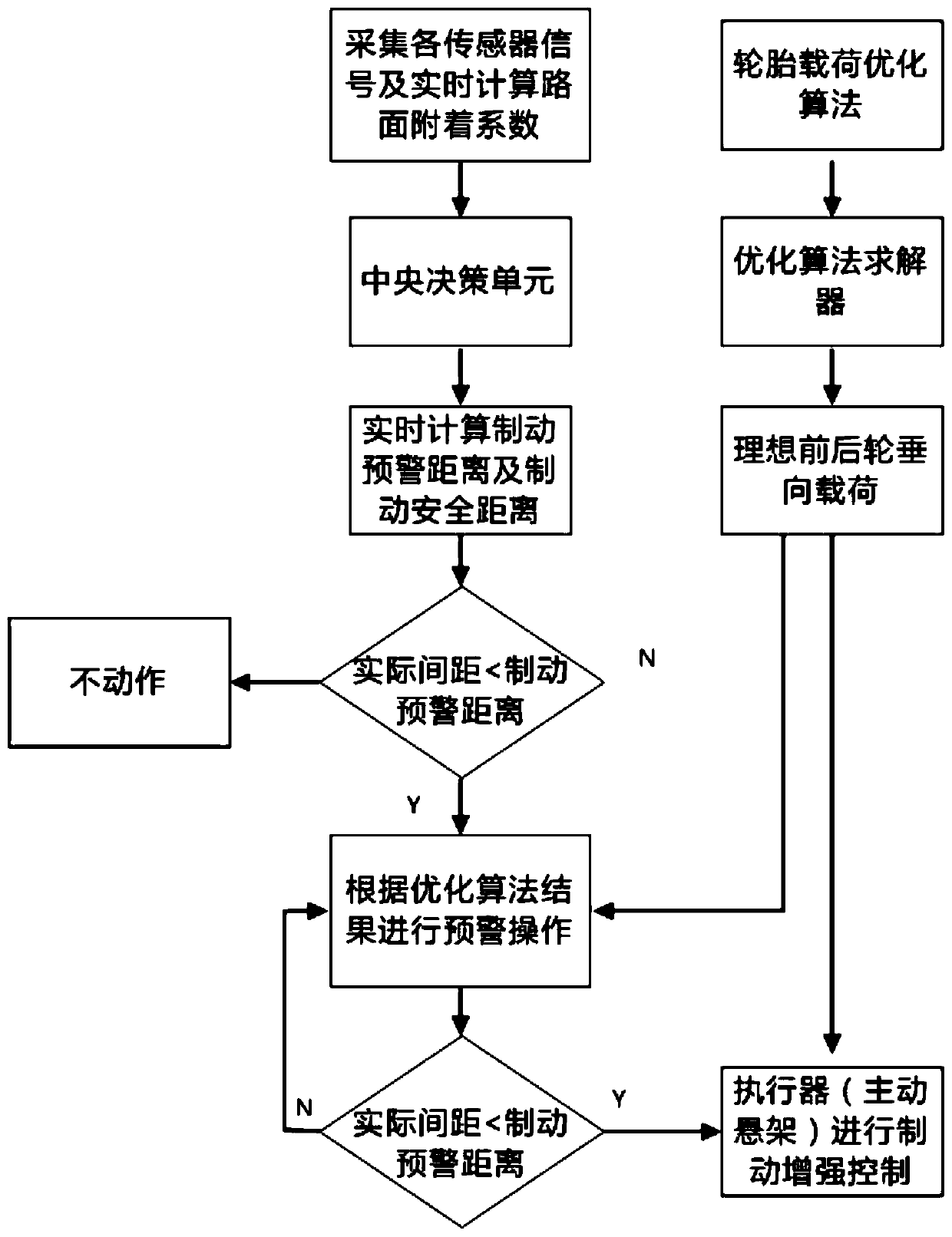
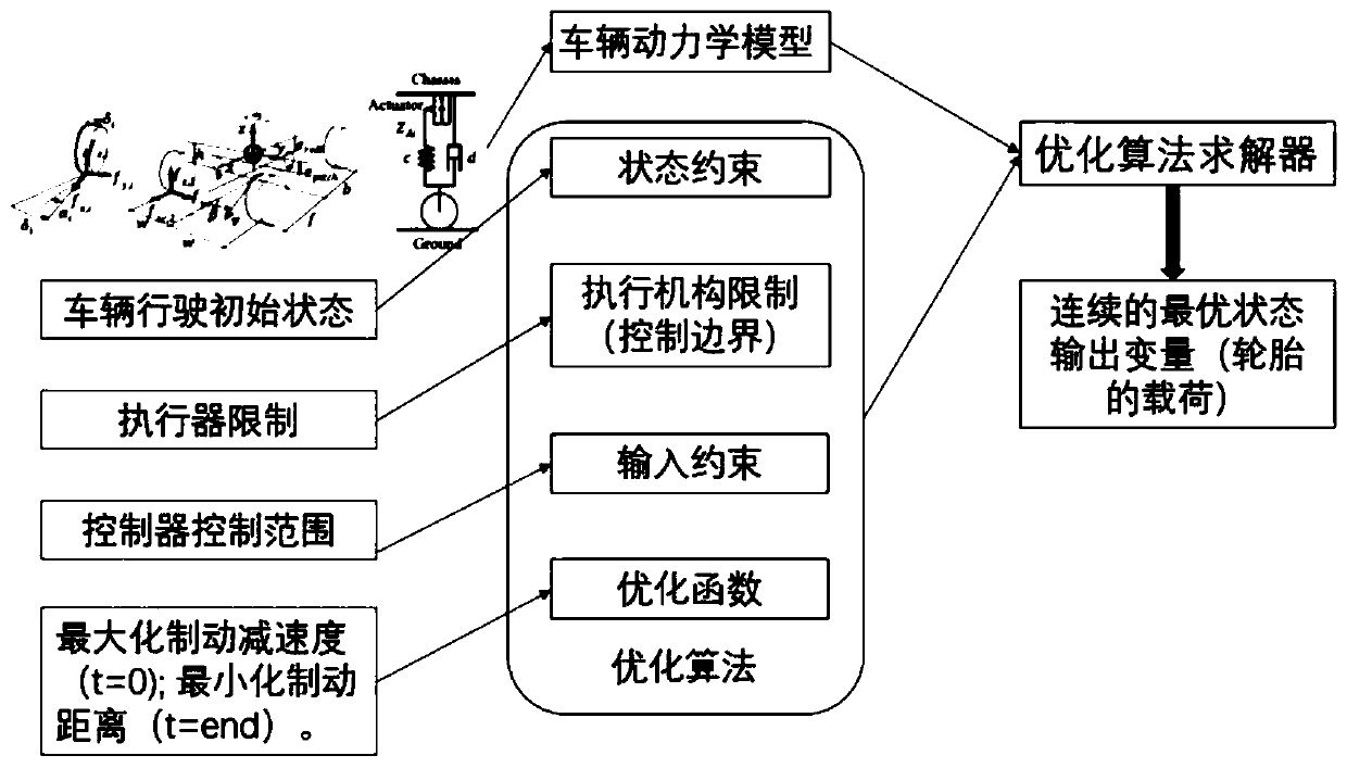
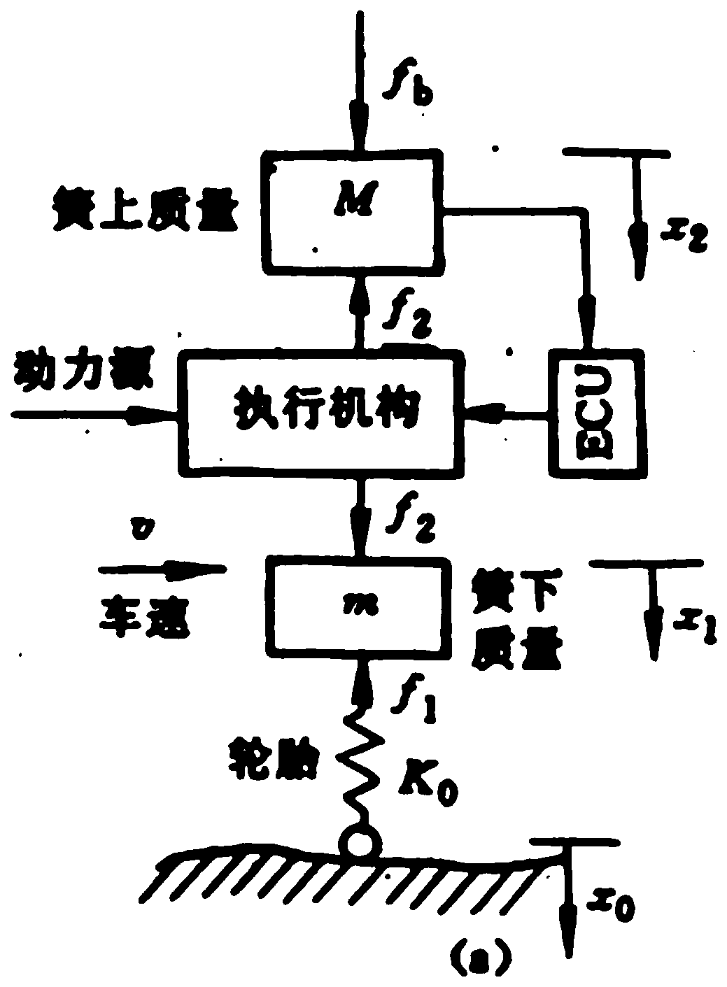
[0025] Such as figure 1 and combine Figure 2 to Figure 4 As shown, an automatic emergency braking assist system based on active suspension control, including the control process, wherein the control process is: Step 1: Collect environmental perception sensors, vehicle height sensors, suspension vertical load sensors, brake pressure sensors , the vehicle speed sensor signal, and the road surface adhesion signal calculated in real time are sent to the central decision-making unit; Step 2: Calculate the warning safety distance and braking safety distance through the central decision-making unit; the calculation of the warning safety distance and braking safety distance here They are all calculated based on the traditional AEB system, without using th...


PUM


Abstract

The invention discloses an automatic emergency brake assisting system based on active suspension control. In the braking warning stage, by adopting the manner of lowering down a front suspension of anactive suspension to a greater degree and lowering down a rear suspension of the active suspension to a lesser extent, forward tilting action of a vehicle during the braking process is simulated, andthe impact of emergency braking on a driver can be reduced; an early warning manner of lowering down the front suspension to a greater degree and lowering down the rear suspension to a lesser extentcan maintain the forward tilting action of the vehicle and reduce the center of gravity of the vehicle; in the enhanced braking phase, an active suspension system is controlled by using an SMC slip film control algorithm and a PID algorithm, so that the vertical load of front and rear axles is always close to the ideal vertical load force calculated by an optimization algorithm to the maximum extent, the role of an ABS is maximized, ground adhesion is fully utilized, the vehicle can reach the maximum braking force and obtain the shortest braking distance during the emergency braking process, and the safety of drivers, passengers and vehicles can be guaranteed to the maximum extent.

Description

technical field [0001] The invention relates to the technical field of automobile safety, in particular to an automatic emergency braking auxiliary system based on active suspension control. Background technique [0002] Smart cars are emerging technologies under the background of a new round of scientific and technological revolution. They use modern sensing technology, information and communication technology, automatic control technology, computer technology, artificial intelligence and other technologies, and represent the strategic commanding heights of future automotive technology. The key to industrial transformation and upgrading is also the development direction recognized by the world. Smart cars have great potential in reducing traffic accidents, alleviating traffic congestion, and improving road and vehicle utilization. [0003] As an important technology in the intelligent driving system, emergency braking system (AEB) has received more and more attention and h...

Claims


Application Information

Patent Timeline
Patent Type & Authority Patents(China)
IPC IPC(8): B60W30/09B60W30/095B60W50/00B60W40/105B60W40/13
CPCB60W30/09B60W30/0953B60W40/105B60W40/13B60W50/00B60W2050/0002B60W2050/0011B60W2420/40B60W2420/403B60W2420/52B60W2710/22
Inventor 张东王慧文宗长富蔡超明
Owner ZHAOQING UNIV
Why Eureka
Try Eureka