Mechanical claw

A technology of mechanical claws and claws, applied in the field of mechanical equipment, can solve problems such as difficulty in meeting production requirements, poor shock resistance, etc., and achieve the effects of large grasping force, strong shock resistance, and stable working conditions

Inactive Publication Date: 2018-09-14
河南浩德科技有限公司
View PDF7 Cites 3 Cited by
  • Summary
  • Abstract
  • Description
  • Claims
  • Application Information

AI Technical Summary

Problems solved by technology

According to the shape of the workpiece held by the robot, there are many types of grippers. As a mechanical gripper for palletizing and grabbing products, the mechanical gripper needs good shock resistance and huge grasping force. The existing mechanical grippers are poor in shock resistance. Difficult to meet production needs

Method used


Image

  • Mechanical claw
  • Mechanical claw
  • Mechanical claw

Examples


Embodiment Construction

[0017] In order to understand the above-mentioned purpose, features and advantages of the present invention more clearly, the present invention will be further described in detail below in conjunction with the accompanying drawings and specific embodiments. It should be noted that, in the case of no conflict, the embodiments of the present application and the features in the embodiments can be combined with each other.

[0018] In the following description, many specific details are set forth in order to fully understand the present invention. However, the present invention can also be implemented in other ways different from those described here. Therefore, the protection scope of the present invention is not limited by the specific details disclosed below. EXAMPLE LIMITATIONS.

[0019] The following combination Figure 1 to Figure 8 The technical scheme of the present invention is described further.

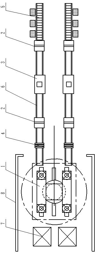
[0020] Such as figure 1 As shown, the present invention proposes a pack...


PUM


Abstract

The invention discloses a mechanical claw. The mechanical claw comprises a mechanical claw frame, air cylinders and claw clamps; the frame comprises a transverse plate and three vertical plates arranged under the transverse plate, connecting clamps are arranged on the middle vertical plate, and rotating frames are arranged on the vertical plates on the left side and the right side; each rotating frame comprises two arc-shaped plates and a rotating column fixed on the arc-shaped plates; the claw clamps are rotationally connected with the rotating frames; each claw clamp comprises tooth claws and tooth claw arms, and the tooth claw arms are rotationally connected with the rotating columns; and one ends of the air cylinders are hinged to the connecting clamps, and the other ends of the air cylinders are hinged to the tail ends of the tooth claw arms. The mechanical claw has the relatively large grabbing force, the working state is stable during product grabbing, and the anti-seismic property is high.

Description

technical field [0001] The invention relates to the technical field of mechanical equipment, in particular to a mechanical claw. Background technique [0002] Robotic grippers can realize robotic parts that function like human hands. The robot gripper is a component used to hold workpieces or tools, and is one of the important actuators. According to the shape of the workpiece held by the robot, there are many types of grippers. As a mechanical gripper for palletizing and grabbing products, the mechanical gripper needs good shock resistance and huge grasping force. The existing mechanical grippers are poor in shock resistance. Difficult to meet production needs. Contents of the invention [0003] Based on at least one of the above-mentioned technical problems, the present invention proposes a new mechanical gripper with high gripping force and stable state when gripping products. [0004] In view of this, the present invention proposes a mechanical claw, comprising: a m...

Claims


Application Information

Patent Timeline
Patent Type & Authority Applications(China)
IPC IPC(8): B65G61/00B65G47/90
CPCB65G61/00B65G47/901
Inventor 崔轩睿
Owner 河南浩德科技有限公司
Why Eureka
Try Eureka