
Unloading device and loading equipment

A technology of unloading device and cargo, which is applied in the direction of loading/unloading, transportation and packaging, conveyors, etc. It can solve the problems of reducing unloading efficiency, unable to unload residual cargo, and difficult unloading of cargo, and achieve the effect of reducing labor

Active Publication Date: 2018-09-14
华腾智达(深圳)智能科技有限公司
View PDF4 Cites 0 Cited by
  • Summary
  • Abstract
  • Description
  • Claims
  • Application Information

AI Technical Summary

Problems solved by technology

However, when the existing loading equipment unloads the goods in the box of the transport equipment by pushing the goods (such as buckets), the goods in the predetermined area can be unloaded by pushing the goods, while the edge areas located on the left and right sides of the predetermined area It is difficult to unload the goods in the area, and it is usually necessary to further manually unload the goods in the edge area, which will reduce the unloading efficiency. It is necessary to improve
[0003] In particular, when the box body of the transport equipment is relatively long, for example, the two sides of the box body of the transport equipment include multiple groups of movable box panels symmetrically arranged, wherein each group of movable box panels has a double-door design, each movable The box board is also adjacent to a movable box board of the adjacent group and the opening direction of the two is opposite. When unloading the goods in the box body of the transportation equipment, generally only the bucket of the loading equipment can be used to unload each group of movable boxes. The box area corresponding to the board (such as Figure 14 and Figure 15 The goods in the predetermined area shown) are pushed and unloaded, but it is difficult to unload the area between adjacent two groups of movable box panels (such as Figure 14 and Figure 15 The remaining goods in the edge area shown) are unloaded, so manual unloading may be required, which reduces the unloading efficiency
In addition, when the loaded goods are heavy bulk materials such as coal and sand, the efficiency of manual unloading is lower, which further reduces the overall unloading efficiency
In addition, when the bottom of the box body of the transport equipment is uneven, the push piece of the existing loading equipment cannot unload the residual goods in the concave part.

Method used


Image

  • Unloading device and loading equipment
  • Unloading device and loading equipment
  • Unloading device and loading equipment

Examples


Embodiment Construction

[0136] The present invention provides an unloading device. In one embodiment, the unloading device can be installed on an existing loader, such as on a bucket of an existing loader, thereby forming a loading device with the existing loader and The loader (that is, the loader is equivalent to the driving device of the unloading device) is driven to unload; in another embodiment, the unloading device can also directly replace the bucket of the existing loader so that A new type of loading equipment is formed with the body of the loader (that is, the body of the loader is equivalent to the driving device of the unloading device) for unloading.

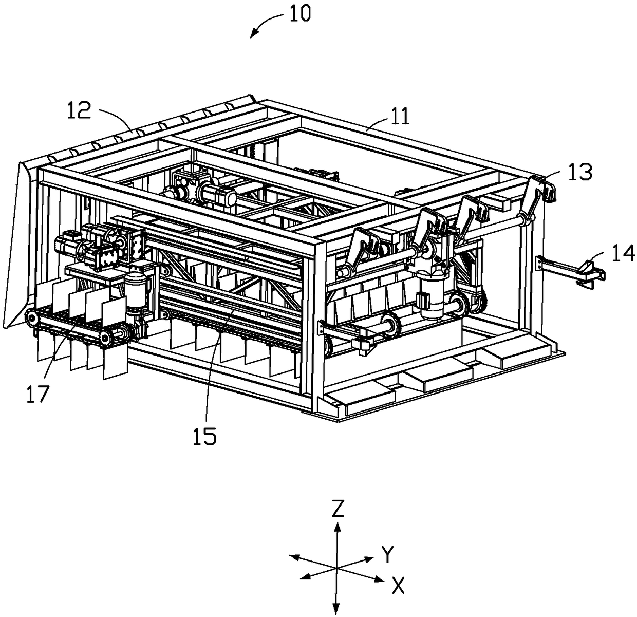
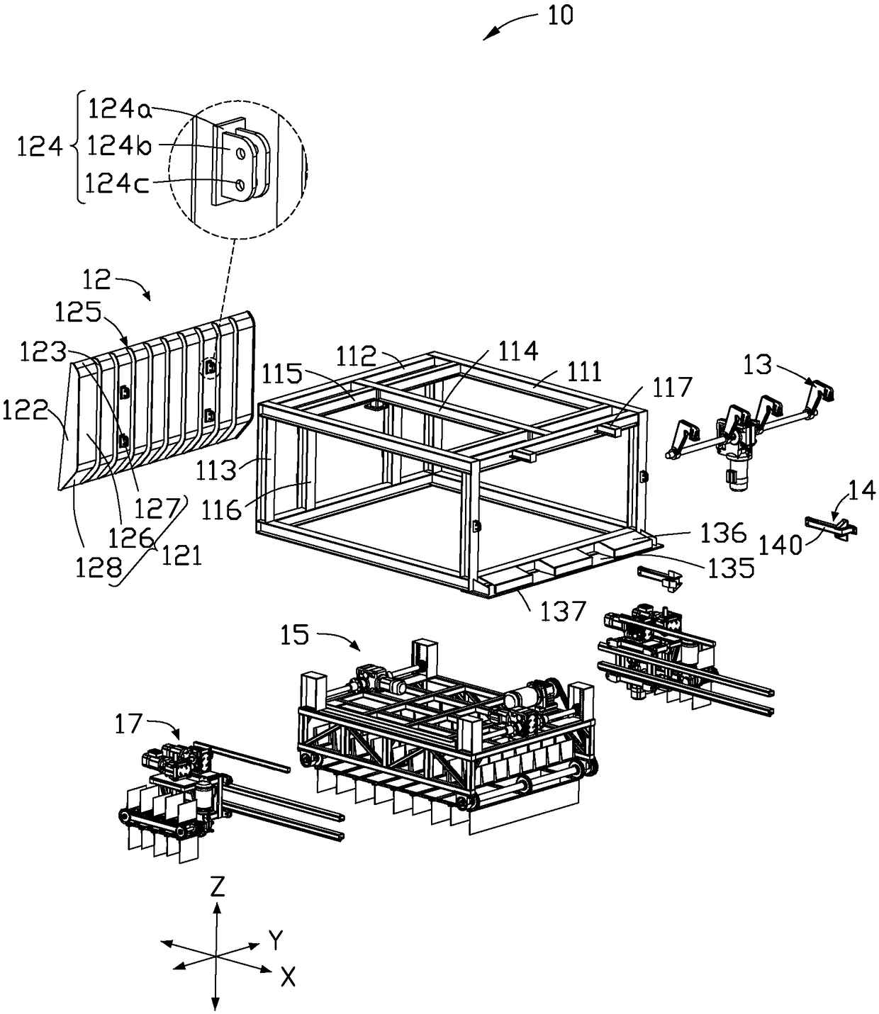
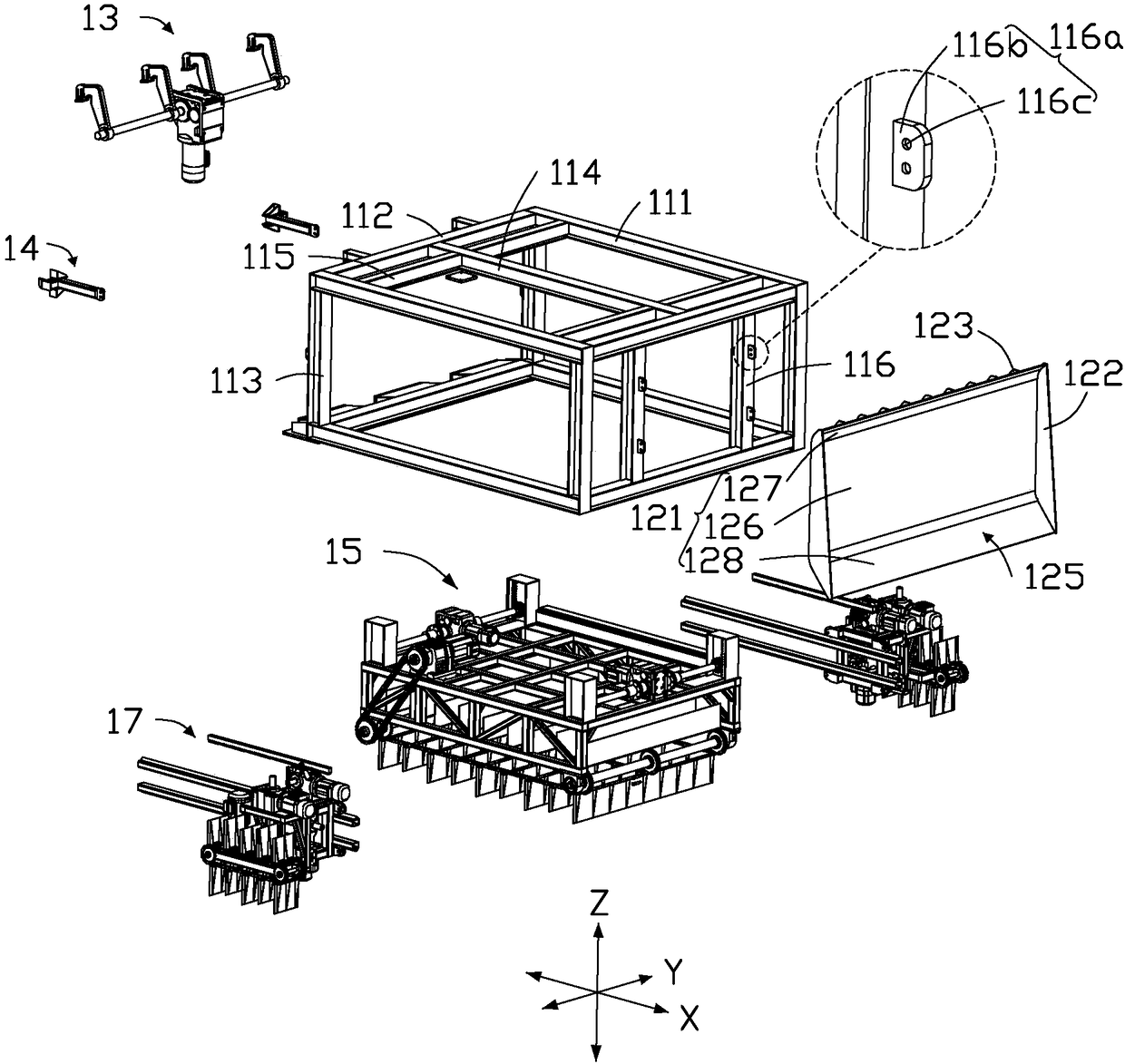
[0137] like figure 1 , 2 In the embodiment shown in , 3, the unloading device 10 installed on the bucket of the existing loader is mainly introduced. The guiding mechanism 14 , the first pushing mechanism 15 , and the second pushing mechanism 17 .

[0138] The support member 11 can be a bracket structure but is not limited to the abov...


PUM


Abstract

The invention relates to an unloading device and loading equipment provided with same. The unloading device comprises a supporting part, a second pushing mechanism and a goods pushing part, wherein the goods pushing part is used for pushing to partially load goods in a predetermined area; the second pushing mechanism is connected with the supporting part and is positioned at the back side of the goods pushing part; the second pushing mechanism is used for pushing goods in an edge area on at least one side of the predetermined area after the goods in the predetermined area are unloaded. The unloading device can reduce manual unloading, and improves unloading efficiency.

Description

technical field [0001] The invention relates to the technical field of loading and unloading, in particular to an unloading device and loading equipment. Background technique [0002] Loading equipment (such as loaders) is a large-scale construction machinery that mainly loads and unloads goods (including bulk materials and small and medium-sized packages, etc.), especially suitable for loading and unloading in mines, infrastructure, road construction, and thermal power enterprises. It is a kind of multi-purpose and high-efficiency construction machinery for excavating, bulldozing, leveling, pushing materials and other operations. However, when the existing loading equipment unloads the goods in the box of the transport equipment by pushing the goods (such as buckets), the goods in the predetermined area can be unloaded by pushing the goods, while the edge areas located on the left and right sides of the predetermined area It is difficult to unload the goods in the area, an...

Claims


Application Information

Patent Timeline
IPC IPC(8): B65G65/04
CPCB65G65/04B65G2201/045
Inventor 范智文
Owner 华腾智达(深圳)智能科技有限公司
Learn More