Laser light source, light emitting device and lamp

A technology of a laser light source and a light-emitting device, applied in the field of lighting, can solve the problems of difficulty and high cost of processing glass aspherical lenses

Active Publication Date: 2018-09-14
杨毅
View PDF5 Cites 12 Cited by
  • Summary
  • Abstract
  • Description
  • Claims
  • Application Information

AI Technical Summary

Problems solved by technology

Glass aspheric lenses are difficult and costly to process

Method used


Image

  • Laser light source, light emitting device and lamp
  • Laser light source, light emitting device and lamp
  • Laser light source, light emitting device and lamp

Examples


Embodiment Construction

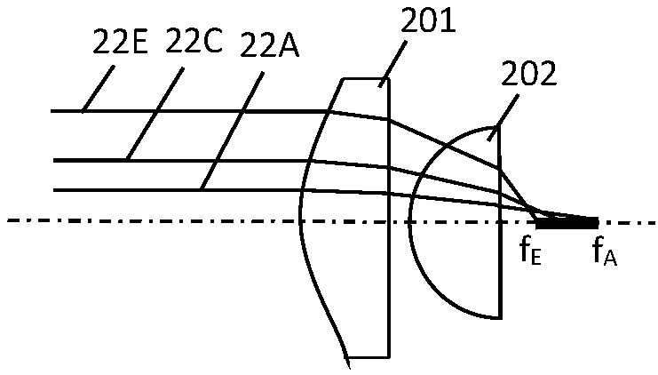
[0016] Before describing the technical solution of the present invention, some deduction of optical principles will be described first. Such as Figure 2a As shown, the spherical convex lens 201 and the spherical convex lens 202 form a convex lens group. Parallel light rays 22A, 22C, and 22E are incident from the left side of the convex lens group, wherein light 22A is close to the optical axis, light 22E is close to the edge of the effective aperture of the convex lens group, and the incident position of light 22C is between light 22A and 22E. Since both 201 and 202 are spherical convex lenses with a real focus, parallel light will form a focus on the right side of the convex lens group. Due to the reason of the spherical surface, the focal points of the incident parallel rays at various positions are not the same, which is the cause of "spherical aberration". The closer the ray is to the edge of the effective aperture, the greater the spherical aberration. Specifically, t...


PUM


Abstract

The invention provides a laser light source, a related light emitting device and a related lamp. The laser light source comprise a laser emitting source for emitting a laser, a first gathering deviceand a second gathering device, wherein each of the first gathering device and the second gathering device is a ball lens or a ball lens set. The laser light source further comprises a fluorescent device located on the optical axis of the second side of the second gathering device, the distance between the fluorescent device and the main face of the second gathering device is smaller than the minimum focal length of the second gathering device, wherein A is larger than or equal to 50 degrees. After sequentially passing through the first gathering device and the second gathering device from theposition near the optical axis, the laser is focused to the fluorescent device, and the fluorescent device generates a received laser. The full spherical surface design is adopted in the second gathering device, the fluorescent device is placed at the proper position within the focus of the second gathering device, emitted light can still be orderly but not crossed, and accordingly the needed optics purpose can be achieved through the rear end optical design. By means of the first gathering device, the focus of the laser incident near the optical axis can be moved forwards to the position of the fluorescent device.

Description

technical field [0001] The invention relates to the lighting field, in particular to a laser light source, a light emitting device and a lamp using the laser light source. Background technique [0002] Laser light sources have been used in automotive headlights and projection displays. The structure of a common laser light source is as follows figure 1 shown. The laser light 121 is incident on the convex lens groups 101 and 102, and is focused on the fluorescent device 103 at the focal point of the convex lens groups through the convex lens groups. The fluorescent device 103 is excited to emit the stimulated light 122 , and the stimulated light 122 is reflected at all angles, most of which are collected by the convex lens groups 101 and 102 and collimated to exit. The dichroic filter located between the laser emitting source and the optical path of the convex lens group is used to transmit the laser light 121 and reflect the received light 122 to separate the two optica...

Claims


Application Information

Patent Timeline
IPC IPC(8): F21K9/64F21K9/69F21V5/04F21V9/35F21Y115/30F21Y113/13
CPCF21K9/64F21K9/69F21V5/04F21V9/35F21Y2113/13F21Y2115/30
Inventor 杨毅
Owner 杨毅
Why Eureka
Try Eureka