
Movably clamping type liquid collecting centrifugal tube

A technology of movable clips and centrifuge tubes, which is applied in the direction of sampling devices and the preparation of test samples, etc., can solve the problems of inability to adjust the height of the liquid collection tube, unstable connection, and inability to fix the liquid collection tube, etc., and achieves ingenious connection structure design, The effect of convenient operation and convenient disassembly

Active Publication Date: 2018-09-14
JIANGSU KEHUA MEDICAL INSTR TECH CO LTD
View PDF7 Cites 3 Cited by
  • Summary
  • Abstract
  • Description
  • Claims
  • Application Information

AI Technical Summary

Problems solved by technology

Existing centrifuge tubes generally include a liquid collection tube, a mounting plate, and a liquid storage tank; the liquid storage tank is used to store liquid, and the liquid collection tube is installed in the liquid storage tank through the mounting plate. However, there is a problem with this structure. The liquid collection tube is generally directly plugged into the mounting plate, and the connection is not stable. Because the liquid collection tube needs to be removed at any time, the liquid collection tube and the mounting plate cannot be integrated. Fixed, so it is necessary to develop a liquid collection tube installation structure that is not only stable but also easy to disassemble; in addition, the height of the liquid collection tube cannot be adjusted, and sometimes the liquid level drops before the liquid collection tube collects enough It is out of the bottom of the liquid collection tube, so a centrifuge tube that can adjust the height of the liquid collection tube is needed

Method used


Image

  • Movably clamping type liquid collecting centrifugal tube
  • Movably clamping type liquid collecting centrifugal tube
  • Movably clamping type liquid collecting centrifugal tube

Examples


Embodiment Construction

[0022] The content of the present invention will be further described in detail below in conjunction with the accompanying drawings.

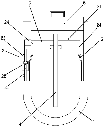
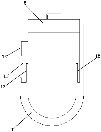
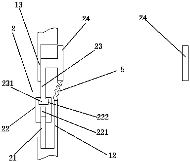
[0023] Such as figure 1 As shown, a liquid-taking centrifuge tube with movable clamping body includes a liquid storage tank 1, an upper cover body 6, a liquid-collecting tube 4, a lifting mechanism 2, an installation block 3, and a telescopic bag 5. The upper cover body 6 is installed on the upper end of the liquid storage tank 1 . Such as figure 2 As shown, the liquid storage tank 1 has a U-shaped structure, and one side of the liquid storage tank 1 is provided with a mounting groove 11 , a limiting plate 13 is provided above the mounting groove 11 , and an isolation ring 12 is provided inside the mounting groove 11 . Such as Figures 1 to 3 As shown, the lifting mechanism 2 includes a support screw 21, a moving block 22, a drive plate 23, and a connecting ring 24. The outside of the support screw 21 is provided with external threads, and ...


PUM


Abstract

The invention discloses a movably clamping type liquid collecting centrifugal tube. The movably clamping type liquid collecting centrifugal tube comprises a liquid storage tank, an upper cover, a liquid extracting tube, a lifting mechanism, a mounting block and a retractable bag, wherein the upper cover is mounted at the upper end of the liquid storage tank; one side of the liquid storage tank isprovided with a mounting groove; the lifting mechanism is composed of a support screw, a moving block, a driving plate and a connecting ring; the mounting block is a flat cylindrical structure and formed by splicing two half-cylinders, and the two half-cylinders are provided with longitudinal semicircular channels and transverse semicircular ring grooves which are corresponding in position; the middle of each longitudinal semicircular channel extends perpendicularly into the corresponding half-cylinder to form the corresponding communicated transverse semicircular ring groove; the outside of the liquid extracting tube is provided with ring-shaped teeth which are clamped and fixed by the transverse semicircular ring grooves of the half-cylinders. According to the movably clamping type liquid collecting centrifugal tube, the liquid extracting tube is firmer in connection, is limited both longitudinally and transversely and further is convenient to dismount.

Description

technical field [0001] The invention relates to a liquid-taking centrifuge tube with movable clamping tube body, in particular to a liquid-collecting tube installation structure of the liquid-taking centrifuge tube. Background technique [0002] At present, the centrifuge tube is a commonly used medical device, which is mainly used for the detection of some liquid samples. The liquid in the centrifuge tube will be divided into several layers after being centrifuged by the centrifuge. After the centrifugation is completed, the liquid in different layers needs to be taken out separately. Existing centrifuge tubes generally include a liquid collection tube, a mounting plate, and a liquid storage tank; the liquid storage tank is used to store liquid, and the liquid collection tube is installed in the liquid storage tank through the mounting plate. However, there is a problem with this structure. The liquid collection tube is generally directly plugged into the mounting plate, a...

Claims


Application Information

Patent Timeline
Patent Type & Authority Applications(China)
IPC IPC(8): G01N1/10G01N1/38
CPCG01N1/10G01N1/38
Inventor 马荣华刘春凤
Owner JIANGSU KEHUA MEDICAL INSTR TECH CO LTD
Learn More