
Method for calculating temperature field distribution of sleeve with inserting and connecting structure

A technology of plug-in structure and distribution method, which is applied in the field of electric power, can solve the problem of incomplete ohmic heating of conductive rods, achieve wide practicability and economy, and reduce design cycle and design costs.

Inactive Publication Date: 2018-09-14
EXAMING & EXPERIMENTAL CENT OF ULTRAHIGH VOLTAGE POWER TRANSMISSION COMPANY CHINA SOUTHEN POWER GRID +1
View PDF6 Cites 8 Cited by
  • Summary
  • Abstract
  • Description
  • Claims
  • Application Information

AI Technical Summary

Problems solved by technology

Therefore, it can be seen that it is not comprehensive to only consider the ohmic heating of the conductive rod

Method used


Image

  • Method for calculating temperature field distribution of sleeve with inserting and connecting structure
  • Method for calculating temperature field distribution of sleeve with inserting and connecting structure
  • Method for calculating temperature field distribution of sleeve with inserting and connecting structure

Examples


Embodiment

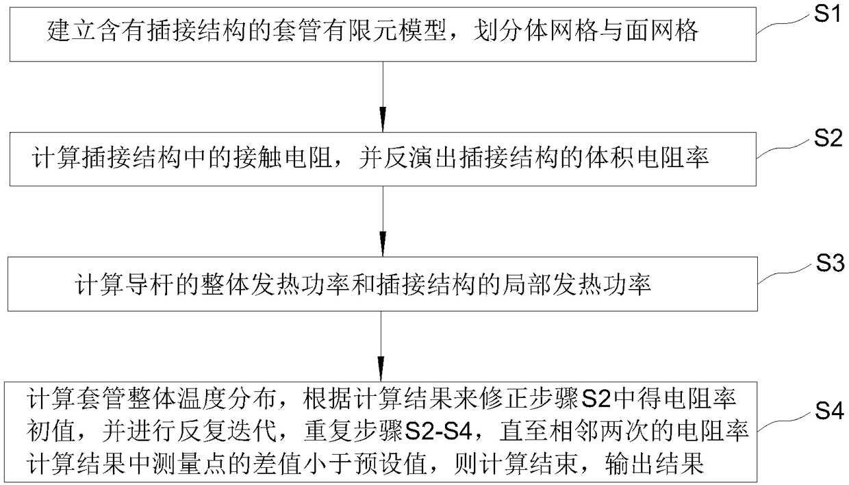
[0027] refer to figure 1 As shown, the method for calculating the temperature field distribution of the casing with a plug-in structure provided in this embodiment includes the following steps:

[0028] S1. Establish the casing finite element model with plug-in structure, and divide the volume mesh and surface mesh

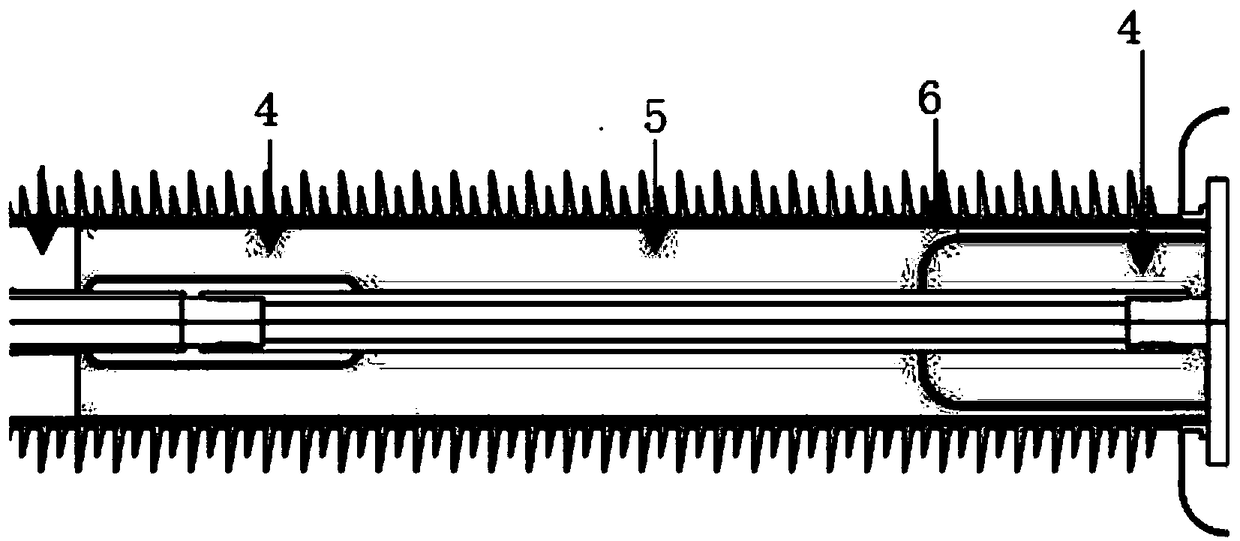
[0029] Use 3D modeling software to build the casing model with plug-in structure, such as Figure 2-3 As shown, the model includes but is not limited to guide rod, epoxy core, SF 6 Necessary structures such as gas 5, flange structure and sheath, transformer oil 1, sheath 2, end fittings 3, internal shielding 6, connection components 4, etc., are imported into the casing model with APDL (ANSYS Parametric Design Language), and can be used for Calculate the finite element analysis model, and establish a grid division program through the APDL language to divide the volume grid in the calculation domain and the surface grid that needs to be coupled in the heat distri...


PUM


Abstract

The invention discloses a method for calculating temperature field distribution of a sleeve with an inserting and connecting structure. The method includes the steps: S1 building a finite element model of the sleeve with the inserting and connecting structure, and dividing a body grid and a surface grid; S2 calculating contact resistance in the inserting and connecting structure, and inverting volume resistivity of the inserting and connecting structure; S3 calculating overall heating power of a guide rod and local heating power of the inserting and connecting structure; S4 calculating bulk temperature distribution of the sleeve, correcting an initial value of the resistivity in the step S2 according to a calculation result, performing repeated iteration, and repeating the step S2-S4 untila difference value of measuring points in two adjacent resistivity calculation results is smaller than a preset value. The method comprehensively considers different heat transfer modes in the sleeve, skin effect of current in the guide rod, contact resistance among joint positions of center conducting rods, watch strap touching fingers and guide rods, overall heat field distribution of sleeves with different connecting structures can be calculated, a heat designing cycle in the designing process of the sleeve is effectively shortened, and the designing cost of the in the designing process ofthe sleeve is effectively reduced.

Description

technical field [0001] The invention relates to the field of electric power technology, in particular to a method for calculating the temperature field distribution of a bushing with a plug-in structure. Background technique [0002] UHV bushing is a key component of many power equipment, such as transformers, valve halls of converter stations, valve halls of rectification stations, etc. It plays a role in supporting conductor extraction and electrical insulation in the power system, and its safe and stable operation is related to the reliability of the entire power system. In addition to the UHV bushing being subjected to electrical and mechanical forces, the temperature gradient distribution caused by the ohmic heating of the central conductive rod and the Joule heating of the insulating medium is also an important factor affecting safe operation. [0003] At present, the calculation of the heat distribution of the UHV bushing is mainly based on numerical simulation metho...

Claims


Application Information

Patent Timeline
Patent Type & Authority Applications(China)
IPC IPC(8): G06F17/50
CPCG06F30/23G06F2113/14
Inventor 张晋寅刘鹏邓军田汇冬韦晓星周士贻周海滨梁晨刘青松潘志城王奇
Owner EXAMING & EXPERIMENTAL CENT OF ULTRAHIGH VOLTAGE POWER TRANSMISSION COMPANY CHINA SOUTHEN POWER GRID
Learn More