Multi-frequency resonant cavity based on metal nano-medium column

A kind of metal nanometer and nanopillar technology, applied in the field of electromagnetism

Pending Publication Date: 2018-09-14
NANJING FORESTRY UNIV
View PDF0 Cites 1 Cited by
  • Summary
  • Abstract
  • Description
  • Claims
  • Application Information

AI Technical Summary

Problems solved by technology

However, at present, the resonant cavity has not been applied to the metal nano-dielectric column alone, so that the resonant cavity can be independent of each other, and can also form a whole, thus forming a multi-frequency resonant cavity

Method used


Image

  • Multi-frequency resonant cavity based on metal nano-medium column
  • Multi-frequency resonant cavity based on metal nano-medium column
  • Multi-frequency resonant cavity based on metal nano-medium column

Examples


Embodiment 1

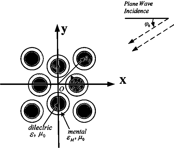
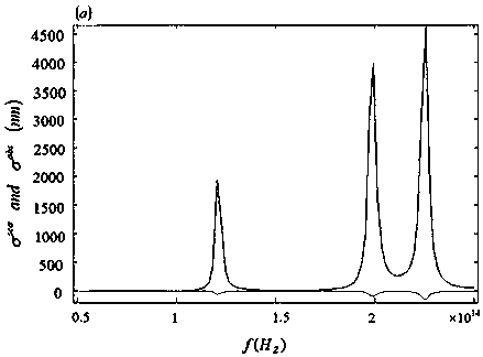
[0050] Example 1: Take period radius R 1 = 85.5nm, R 2 =116.67nm two-layer 8-cylindrical structure model as an example, the outer radius r of the nanowire of the metal (Ag)-dielectric cylinder 1 =60nm, medium core radius r 2 = 45nm, the thickness r of the metal layer 1 -r 2 =15nm, the dielectric constant of the medium ε / ε 0 =10 and the frequency range is f=5e13~2.5e14H z cylindrical periodic structure. figure 2 The three resonant frequencies in the middle are f=1.2268e respectively 14 h z , f=2.0038e 14 h z and f = 2.3045e 14 h z Corresponding to the three field distribution diagrams of Fig. 4(a), Fig. 4(b) and Fig. 4(c), it can be seen that the same three resonant frequencies are from small to large, and the three frequency resonant cavities are respectively composed of four nanopillars in the middle. body, four nanopillars inside and outside to form an outer cavity, and a large cavity synthesized inside and outside.

Embodiment 2

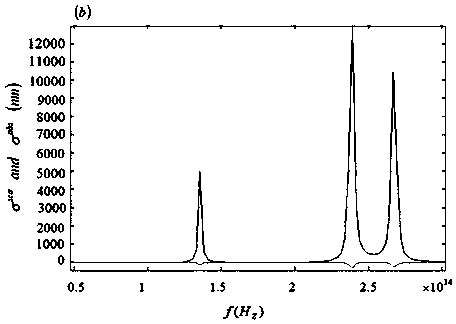
[0051] Example 2: The period radius is still R 1 = 85.5nm, R 2 =116.67nm two-layer 8-cylindrical structure model as an example, the outer radius r of the nanowire of the metal (Ag)-dielectric cylinder 1 =60nm, medium core radius r 2 = 30nm, the thickness r of the metal layer 1 -r 2 =30nm, medium core permittivity ε / ε 0 =10 and the frequency range is f=5e13~3e14H z The cylindrical periodic structure of image 3 The three resonant frequencies in the middle are f=1.3687e respectively 14 h z , f=2.4192e 14 h z and f = 2.7626e 14 h z Corresponding to the three field distribution diagrams of Fig. 5(a), Fig. 5(b) and Fig. 5(c), it can be seen that the same three resonant frequencies increase from small to large, and the resonant cavities are also composed of four nanopillars in the middle. The inner and outer four nanopillars form the outer cavity, and the inner and outer composite large cavity.


PUM


Abstract

The invention discloses a multi-frequency resonant cavity based on a metal nano-medium column. The multi-frequency resonant cavity comprises 8 metal-medium nano pillars, 4 metal-medium nano pillars inthe 8 metal-medium nano pillars are symmetrically distributed at an inner layer circular region boundary with a periodic radius R1, the other four 4 metal-medium nano pillars are symmetrically distributed at an outer layer circular region boundary with a periodic radius R2, and the length of R1 is smaller than that of R2. The characteristics of metal and medium surface plasma waves are used, theresonance of an external light or electromagnetic signal inside a structural unit through the plasma waves is achieved and is different from resonance caused by a traditional resonant cavity source inan internal part, at the same time, a plasma wave effect is used between the nano pillars to form resonance, thus resonant cavities can be independent of each other and can form a whole body, and a multi-frequency resonant cavity is formed.

Description

technical field [0001] The invention belongs to the field of electromagnetic technology, in particular to a multi-frequency resonant cavity based on metal nano-dielectric columns. Background technique [0002] Electromagnetic waves are oscillating particle waves that are derived and emitted in space by electric and magnetic fields that are in phase and perpendicular to each other. They are electromagnetic fields that propagate in the form of waves and have wave-particle duality. Under the excitation of electromagnetic waves, the light wave is coupled with the plasmon in the metal, and surface plasmon resonance is generated at the free space-metal and metal-medium interfaces. When metal and dielectric composite nanowires form a certain space, adjacent plasmon waves form plasmon wave resonance in the cavity. Since the multilayer composite nanowires form different cavities, the plasmon waves formed by different incident waves can resonate in different cavities, forming a multi...

Claims


Application Information

Patent Timeline
Patent Type & Authority Applications(China)
IPC IPC(8): H01P7/06H01P7/10
CPCH01P7/06H01P7/10
Inventor 余观夏董隽媛付晶晶杜文文骆敏
Owner NANJING FORESTRY UNIV
Why Eureka
Try Eureka